Welcome to Tesla Motors Club
Discuss Tesla's Model S, Model 3, Model X, Model Y, Cybertruck, Roadster and More.
Register

20 Amp GFCI trips with mobile connector.

This site may earn commission on affiliate links.
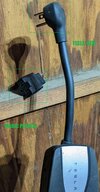
Question: Does this 5-20 to 5-15 converter have a ground pin? Or is it one of those converters that have a pigtail or screw terminal and you're supposed to screw it onto a ground lug? If it's only a two prong plug (i.e., missing the ground pin), does it have polarized blades (one thicker than the other)?
 

Attachments

  • Plugs.jpg
    Plugs.jpg
    471.3 KB · Views: 124
  • Plugs2.jpg
    Plugs2.jpg
    390.9 KB · Views: 96
Last edited:
So, to summarize and to see if I understand everything:
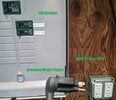
  • A regular 5-20 / 5-15 GFCI outlet protected by a 20A breaker in what looks like a 100A sub-panel.
  • Assume that the wire gauge is correct for such a short run (12AWG, I believe).
  • I understand now why you are able to get > 12A when charging. You're using the 5-20 NEMA adapter with the mobile connector. Earlier I mistakenly assumed that you were using a 5-15 adapter and questioned how you were going to set 13A+ as the charging level.
  • Plugging the NEMA 5-20 adapter directly into the 5-20 outlet (no converter used) causes the GFCI to trip (as opposed to the main 20A breaker).
  • Using the "extra plastic" of the 5-20 to 5-15 converter between the MC and the 5-20 outlet, it does not trip at 16A.
I'm at the point of grasping for straws to come up with useful advice. I guess the only thing I can suggest is making sure that you have at least 12AWG wire and that all of the terminal connections on the back of the socket are tight. I'm hoping that the electrician did not use the "back stabbing" terminals of the outlet and instead used the screw terminals. Those are the ones were you simply strip the wire and shove it into a hole on the back or side of the outlet. If you do this inspection be sure to put both the main 100A breaker and the 20A circuit breaker that your 5-20 outlet is on, OFF. Even then, plug something into the outlet (like a light) and make sure it's de-energized.

Use of the 5-20 to 5-15 plug converter also means that the NEMA 5-20 plug on the MC is moved further away from the actual socket. This can be important because there is a temperature sensor inside the plug which is designed to monitor the socket for overheating. When you place a plug converter (or extension cord) inline with the NEMA adapters, you will negate this protection (to a degree). I believe that in most cases, an overheat outlet/plug condition will cause the car to automatically lower the charging current, not trip the GFCI.
 
More clarifying data

My initial (disappointing/confusing) experience was that setting the 5-20 plug directly into the 5-20 outlet was tripping the GFCI at 16A.

In frustration I attached the 'Magic Plastic' as a hail mary, but that was in concert with setting the Tesla to only pull at 13A, then 14A.

This evening I tried setting the Tesla at to pull 15A and it tripped the GFCI (even with the Magic Plastic). I then tried without the Magic Plastic and it also tripped at 15A.

My current postulate is that the outlet is a might too sensitive, and at 15A+ it trips.

Tomorrow I'll try 14A without the Magic Plastic (I think I tried it tonight and it tripped, but I'll confirm in the morning).
...there is a temperature sensor inside the plug which is designed to monitor the socket for overheating. When you place a plug converter (or extension cord) inline with the NEMA adapters, you will negate this protection (to a degree)
That is not my experience. In my prior setup I had the 'magic plastic' plugged into a 10 Gauge Extension Cord that was thrown over a wall and plugged into a GFCI 5-15 outlet (that had a 20A breaker feeding it). In that old scenario the Tesla would REGULARLY detect overheating and reduce the charge rate. Since I moved to the 5-20 I have not seen a single overheat and reduction warning (just the GFCI trips).
 
My understanding of the workings of a GFCI outlet is that it does NOT protect against over-current situations. That's the function of the breaker in the electrical panel. The GFCI is supposed to trip when it detects a leakage path that should not normally be there; in other words, an electrocution scenario. I will wait for someone who is an expert in these matters to address this point.
 
More clarifying data

My initial (disappointing/confusing) experience was that setting the 5-20 plug directly into the 5-20 outlet was tripping the GFCI at 16A.

In frustration I attached the 'Magic Plastic' as a hail mary, but that was in concert with setting the Tesla to only pull at 13A, then 14A.

This evening I tried setting the Tesla at to pull 15A and it tripped the GFCI (even with the Magic Plastic). I then tried without the Magic Plastic and it also tripped at 15A.

My current postulate is that the outlet is a might too sensitive, and at 15A+ it trips.

Tomorrow I'll try 14A without the Magic Plastic (I think I tried it tonight and it tripped, but I'll confirm in the morning).

That is not my experience. In my prior setup I had the 'magic plastic' plugged into a 10 Gauge Extension Cord that was thrown over a wall and plugged into a GFCI 5-15 outlet (that had a 20A breaker feeding it). In that old scenario the Tesla would REGULARLY detect overheating and reduce the charge rate. Since I moved to the 5-20 I have not seen a single overheat and reduction warning (just the GFCI trips).
How long is that extension cord and how far from the outlet was it uncoiled? Were you also trying to overload it beyond 12A or using it at 12A?
I used a 50 ft 12/3 extension cord with my garage 5-15 GFCI Outlet with the Tesla 5-15 adapter and didn't get heating related trips.
 
Last edited:
My understanding of the workings of a GFCI outlet is that it does NOT protect against over-current situations. That's the function of the breaker in the electrical panel. The GFCI is supposed to trip when it detects a leakage path that should not normally be there; in other words, an electrocution scenario. I will wait for someone who is an expert in these matters to address this point.
Not an expert, but it is easy to find online that a GFCI outlet is not designed to protect against overcurrent.
Residual-current device - Simple English Wikipedia, the free encyclopedia

That said, when you overload one, it can still trip. This can be from a variety of reasons. The overloading can put the transformer into an operation region where it trips unnecessarily. It can also be that such a larger load is typically of the type that is highly capacitive or inductive (like motors for example) that can cause that imbalance to trip the GFCI.
 
GFCI, a dubious solution to an almost nonexistent problem…. IMO of course.

I would replace the outlet with a standard 5-20 and upgrade the breaker to GFCI. Prolly solve things. For whatever reason my experience has been much better with GFCI breakers. Ymmv.

The car setting is, short of setting below 16a, irrelevant. it can request all it wants, won’t matter. the Telsa mobile connector EVSE, with the 5-20 pigtail, will only deliver 16a.

I would remove the ”magic plug”.
 
Last edited:
  • Like
Reactions: Eric33432
That is not my experience. In my prior setup I had the 'magic plastic' plugged into a 10 Gauge Extension Cord that was thrown over a wall and plugged into a GFCI 5-15 outlet (that had a 20A breaker feeding it). In that old scenario the Tesla would REGULARLY detect overheating and reduce the charge rate. Since I moved to the 5-20 I have not seen a single overheat and reduction warning (just the GFCI trips).

there is a belief among some that above use of a 5-15 is acceptable. It requires a belief that the 5-15 is built adequate to support 20a (granted I’ve seen tear downs that suggest this is so), the assumpton that no other device on that branch circuit is on, the hope that all interconnections on the branch are good, and then decision to overlook NEC directive that EV charging be on dedicated circuits. as it happens i keep the same kind of adapter in my MC for just such a situation, but do know that’s sort of a stretch best practice.
 
Update:

I've tested 14A with and without the 20-15 converter and it trips

I've tested 13A with and without the 20-15 converter, and it 'sometimes' trips.

Each time it trips the M3LR sets the charging to 48A (max). This is the piece of info that concerns me. I fear that there might be something odd going on, but it may just be standard behavior (an odd standard in my view).

Last night I plugged in and set it for 12A - no trip all night.

Anyone know a simple way to defeat the GFCI in an plug?
The obvious thing to do is to REPLACE the GFCI with a new one. That one is tripping when it shouldn't.
 
Each time it trips the M3LR sets the charging to 48A (max). This is the piece of info that concerns me. I fear that there might be something odd going on, but it may just be standard behavior (an odd standard in my view).
That definitely has nothing to do with anything. The cars always just show the default number on the display of the capability of the onboard charger whenever it is disconnected. So when it's not plugged in, it will show 48A. When a breaker trips, that's effectively the same as the car thinking it's not plugged in, so again it will flip the display back to showing 48A.

When it is actually connected, then it checks what adapter is being used and reads the chip in it to get the correct amp limit and uses that. The 48A thing on the display isn't part of this.
 
  • Like
Reactions: android04
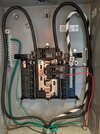
Okay, thanks for that view. Previous photo from you marked the top 20A breaker as being the 5-20 outlet. That's the black (hot) wire going into the breaker. AFAIK, wires generally have printing on them indicating what gauge is under the insulation. If those three wires (black, white, green) are actually from a bundle, then the gauge is probably printed on there. Anybody willing to guess the gauge based upon this photo? 12AWG is just a bit larger than 5/64", according to my Gage-It Hardware Gauge.

Something doesn't look right to me... I'm not a professional electrician but... The red wire coming out of the grommet at the bottom of the panel does not seem to have any matching white (neutral) or green (ground) wire with it. Is that red wire supposed to be for the 5-15 outlet? If so, then maybe a shortcut was used. Like daisy-chaining the neutral and ground between the two sockets. I don't know if that's allowed by code.

What I'm more interested in is the 5-20 outlet. If you can open up the socket (breakers off first), find out how the wires have been attached: pushed in or using the screw terminals. If they are pushed in, I'd pull them out and use the screw terminals. If they are already on the screw terminals, then make sure that they are tight.
 
If the 5-20 GFCI is tripping then replace the GFCi receptacle. Or retighten the screws on the back.

The reason there’s only one neutral (white) wire for two circuits is that it is shared between the two circuits which is a fairly common installation practice. Just don’t move those two breakers apart from each other because a shared neutral will only work correctly if each breaker is on a different leg of the split phase.
 
This is a very hard thread to follow, partly because the OP insists on using goofy language for the parts he is using, such as 'Magic Plastic'.

I came here looking for info on what is going on with using GFCI on the outlet the mobile connector is plugged into. My understanding is this is part off the NEMA code, so is required, and no way around that. I'm not putting anything in my home that isn't up to snuff.

I can't understand why a pair of cascaded GFCI devices would have any impact on each other. The GFCI is just a toroid transformer core, with both sides of the power line wound through it. The polarity of the windings is such that the two will cancel as long as they are equal. When unequal, a net flux causes current to flow in a sense wire wound on the same core, which can be sensed and used to trip a relay. There is no reason to think having a second GFCI downstream of the first, would cause any problem with operation of either. Yet, I see this reported repeatedly.

I don't see where anyone in this thread explains why this would be a problem. More importantly, I don't see where anyone has a solution.

To the best of my knowledge, all EVSE contain a GFCI, in fact, I believe it is required in the spec. NEMA requires a GFCI in the outlet in locations like the garage. I don't see how EVSE makers can be selling these devices without having problems with them. The only solution would seem to be to not use an outlet, rather direct wire the EVSE.
 
  • Like
Reactions: Rocky_H