You guys are killing me! No no no! Ohm’s law is not for pure resistive loads only, it applies just as well to coil impedance (resistance and reactance) such as a motor coil. At least you’re not claiming that current will go down as I apply more voltage to a DC motor, unlike a few of the other helpful posts here.
You make a good point that on ICE cars, there will be more than 12V on the 12V outlets while the engine is running. And it is reasonable to assume that the EEs designing these inflators have taken this into account. So you are probably right that most or all of these will work just fine at 16V. Still, I wish they would just include a spec sheet stating a voltage range rather than just 12V.
The people claiming current will go down with voltage is correct for a load like an air compressor if the compressor's load is being limited by the resistance to the air being pumped. Because of back emf, a motor can't be modeled as a resistor in this case.
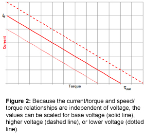
See example of motor resistance vs torque:
DC Motors - current, voltage, speed, power, losses and torque relationships - PCB 3D
Sure, if the compressor is not facing resistance, a higher voltage will typically mean more rpms and more current (and more air flow), but this is not the case when there is a load that is resisting your compressor's efforts.
See relation of current vs torque (article also goes into detail how back emf plays its role), you can see for a given current, higher voltage provides more torque, which in turn means that less current is needed for the same torque.
Tutorial: Brushed DC Motors, Part II
Example of how the current draw of a compressor varies with load:
Pic 1 - Pumping to Atmosphere - 30 amps
Pic 2 - Pumping an AT tyre from 1.6 to 2.8 bar - 34 amps
Powering a 12v Air Compressor
Note above assumes the compressor is just wiring the 12V directly to the motor and does not have a motor controller. If it does have a motor controller, it may be constant current or constant speed (or has similar limiters), in which case the analysis changes. It also matters if the compressor has an air tank or not.
Others already pointed out however, 12V air compressors are typically already designed to work in a wide voltage range. If run directly from the battery, it can sag down to 11V. If running off a car that is on, the alternator may be putting out up to 15V. If you buy a compressor for cigarette sockets that has a rated current within the margin given for the socket (12A continuous 16A peak), it should still work fine, because regardless of if the voltage might increase current in certain cases, that would be within the margin.
I would note also, most compressors recommend you keep the engine running when running them, if that higher voltage was bad for the compressor, I imagine they would not make that recommendation.
As noted by others, Tesla's warning is only about inverters, as they are more sensitive to the exact voltage (as discussed above, some have overvoltage detection circuits which will shut down inverter if it detects 16V).
Model 3 Owner's Manual | Tesla