Welcome to Tesla Motors Club
Discuss Tesla's Model S, Model 3, Model X, Model Y, Cybertruck, Roadster and More.
Register

Tesla Model S 2014 HV Battery issue

This site may earn commission on affiliate links.
Hi, I have a Model S 2014 P85+

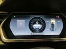
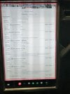
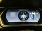
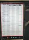
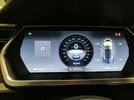
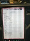
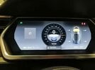
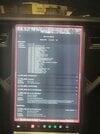
Last Monday I was driving it near from my house in Guatemala, but the car suddenly stoped with the warning: “Unable to drive, supply voltage too low”… I thought that would be a 12V battery failure, so, on my own, I replaced it for a new one. Yesterday, after installed it, the car woke up with 13 alerts on it, so I put it on “Service Mode” and take some pictures of the screen (please find them attached to this email),

2.jpeg


The more stressful alert for me was: BMS_f080_SW_Int_HV_Disconnect: the BMS has detected that the HV battery pack voltage differs from the sum of the brick voltages, making the HV battery unavailable for charging, driving or supporting the LV battery…

It look like is something is either not connected completely or properly from the battery, or maybe a problem with the HV battery itself?

Can somebody help me, where should I start to solve this problem?

Thanks a lot for your valuable help!

Juan Carlos
 

Attachments

  • 9.jpeg
    9.jpeg
    89.5 KB · Views: 406
  • 8.jpeg
    8.jpeg
    139.8 KB · Views: 317
  • 7.jpeg
    7.jpeg
    87.7 KB · Views: 297
  • 6.jpeg
    6.jpeg
    176.4 KB · Views: 288
  • 5.jpeg
    5.jpeg
    90.6 KB · Views: 279
  • 4.jpeg
    4.jpeg
    179.5 KB · Views: 277
  • 3.jpeg
    3.jpeg
    90.8 KB · Views: 273
  • 2.jpeg
    2.jpeg
    125.3 KB · Views: 314
  • 1.jpeg
    1.jpeg
    138.6 KB · Views: 456
Very new to this game but my 2016 Model S (UK variant) gave similar messages in some respects with warnings about no suspension, Cant Start, low voltage, etc. After a hard reset, these messages disappeared and I was left with a warning message that my 12v Battery voltage is too low and I should take to a Service centre for replacement. In all other respects the car operates and drives fine. This message will not cancel until battery is replaced. In looking up how to do this on YouTube, a couple of videos warn of dire consequences if the high voltage connector is not disconnected BEFORE disconnecting the 12v Battery. I'm just wondering if that was done before you removed your battery - apparently it wrecks the software if you don't, which maybe results in all kinds of spurious and possibly erroneous error codes? Just a thought.

According to Tesla service manual. Disconnect is 12V -> 1st resp loop for all configurations <= 2020. But auto repair manuals have been known to be wrong before :) Interested in the warning links if you have them.

Reconnect is where there is more ambiguity...

 
Upvote 0
Replaced the BMS, 6 BMBs , battery coolant heater and fuse. bms_u029 max charge limit error is gone. But now I have these fun codes. I charged each module to 24.0 V from their original state of battery tear down at 20.7V (18mi range left) when battery was installed my range available is 28mi but the most concerning code is module voltage not matching the sum of the bricks. I should also note that the total voltage between the both fuse terminals was 130V but should have been roughly 385V….when testing voltage of one terminal and a terminal of the modules in the pack the voltage was above 300V …there is some kind of disconnect.
 

Attachments

  • 6DFAE524-0466-422D-8CC3-14E6D216AE1B.jpeg
    6DFAE524-0466-422D-8CC3-14E6D216AE1B.jpeg
    510 KB · Views: 392
Upvote 0
Replaced the BMS, 6 BMBs , battery coolant heater and fuse. bms_u029 max charge limit error is gone. But now I have these fun codes. I charged each module to 24.0 V from their original state of battery tear down at 20.7V (18mi range left) when battery was installed my range available is 28mi but the most concerning code is module voltage not matching the sum of the bricks. I should also note that the total voltage between the both fuse terminals was 130V but should have been roughly 385V….when testing voltage of one terminal and a terminal of the modules in the pack the voltage was above 300V …there is some kind of disconnect.

Intersting, hard to imagine how to get 130v if modules are correctly connected serially. Kind of doubt there are any programmable junctions between modules (but don't know, haven't yet opened a pack) However, Recell-EV seems to be able to remove bricks from the serial chain. Wonder if thats just changing physical connections. Also hard to imagine the output contactors causing this... Also can't imagine any load that would draw down to 130v from 300+ at these current levels.

Strange...
 
Upvote 0
Replaced the BMS, 6 BMBs , battery coolant heater and fuse. bms_u029 max charge limit error is gone. But now I have these fun codes. I charged each module to 24.0 V from their original state of battery tear down at 20.7V (18mi range left) when battery was installed my range available is 28mi but the most concerning code is module voltage not matching the sum of the bricks. I should also note that the total voltage between the both fuse terminals was 130V but should have been roughly 385V….when testing voltage of one terminal and a terminal of the modules in the pack the voltage was above 300V …there is some kind of disconnect.
I thought replacing BMS wasn't advised since it contains history of cells behavior... Was it new or used? was its data reset?

Where are u measuring 130V? between Pyro terminals?
Full voltage should be between positive/negative contractors HV terminals, as far as i understand.
 
Upvote 0
Hi

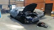
I make a try to get some help as I start to get stuck now. I’m from south of Sweden by the way and try to fix my Tesla 🙂. Narrowed down the failure I believe, but not sure.

Car: Tesla Model S 2015, 85 kWh battery

Issue code: F123 internal isolation
I can measure voltage between minus and chassis and also plus and chassis at multiple positions. (Voltage between 10-130)

No water in battery pack.

When module 16 is mounted I have isolations issue.

At the position for module 16, I have contact between minus and chassis, measured value 10.05 MOhm. The buzzer on the multimeter does not beep. (This 10,05 Mohm disappears when contact for contactors is disconnected, read further down)

When installing module 16 in position 16 = isolation fault.
When installing module 15 in place 16 = isolation fault.
No isolation fault when modules 1, 2, 3, 14, 15 are mounted. When 16 are installed, there will be isolation faults on all the above modules.
The above tells me it has nothing to do with the modules!

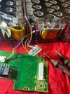
When I disconnected the cables to the contactors, the isolation fault disappeared. Then I connected the cables to the contactors again and loosened the connector (blue arrow) for the contactors on the BMS board, then the isolation fault disappears. All other cables are disconnected to the BMS board. When the cable is mounted on the BMS board (yellow arrow), I have isolation fault.

Would you say that the main BMS card should be replaced?

All help is appreciated!

BR Richard

19FF36AE-32E1-41CE-9B45-3E67A2460551.jpeg

92822FF6-7049-4CD0-B01D-0A54DD546B2C.jpeg
 
Upvote 0
I can measure voltage between minus and chassis and also plus and chassis at multiple positions. (Voltage between 10-130)
Normal when HV is connected to BMS (as u already found out)
I had the same voltage before i disconnected HV plug from BMS
At the position for module 16, I have contact between minus and chassis, measured value 10.05 MOhm.
Thats plenty good isolation.
Normal Open contactors iso is >3MOhm, and with closed ~1.6Mohm
When I disconnected the cables to the contactors, the isolation fault disappeared.
Thats how it should be.
U can't measure isolation on live circuits...
 
Upvote 0
if u have no isolation with bms plug removed then yes sounds like no problem
idk leafs system but hv should not be connected anywhere while testing. BMS has connection to ground on purpose, thats how it monitors isolation...
maybe u had water before n its dried up now?
most common source is thru pyro fuse cover

whats the story with the car? any other codes besides f123?
looking at the rear cover, lots of corrosion there so looks like water was there n close to HV plug...
also water likes to hide under those emf shields check if its wet under it

its also possible that BMS board might be bad but thats very rare...
 
Upvote 0
Actually there was minor water in the battery, but I would say condens on black water pipes inlet and outlet from the battery. Color of water is like drinking water. And also condense at module 9 in the front top. But I thought it happened due to that I empty the battery on coolant water with high pressure gun. Maybe there was a small water leak inside!

Story: Car was at Tesla and got new hardware fuse and new umbrella valves. Car/Battery was classified as risk/fire and must replace battery. Battery is a reman battery. Maybe replaced 2017.

I have removed the BMS and no water under. All modules have been removed, no water. Very clean battery! You write water in “emf chields”. Where is the position of this emf chields?

See attached picture for all fault codes.

Next plan is to find an another cable between BMS and car and extend it, so I can try the battery outside the car. Do you think I should assemble all moduls and try the battery again with the extended cable?

I have not really done anything with the battery except maybe dried out the condense. Or what can be the next step?

0F763B99-270B-4EF0-A7D8-7A04625C5B96.jpeg
A4300F95-12B7-443A-9703-CD8A28BA0B00.jpeg
607FC913-A37C-4F55-9BE0-4E5CD53A8226.jpeg
 
Upvote 0
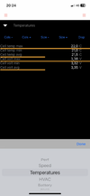
I also have cell imbalance at 58mV, and as I have been informed it’s too much. Should max be 35mV. Correct? But this shouldn’t affect the isolation issue, do you agree? See attached pictures.
 

Attachments

  • BCC03528-A06B-4A31-BABE-9FA720BBFEF0.png
    BCC03528-A06B-4A31-BABE-9FA720BBFEF0.png
    233.9 KB · Views: 49
  • 0A21B9DC-2893-41BC-94FA-1AEAE186E320.png
    0A21B9DC-2893-41BC-94FA-1AEAE186E320.png
    230.9 KB · Views: 46
  • 7FA90931-F862-4003-A987-F2C9E2ED4183.png
    7FA90931-F862-4003-A987-F2C9E2ED4183.png
    174.7 KB · Views: 32
  • 69BD0EE7-A210-48AA-811C-2E1A4FF99EA8.png
    69BD0EE7-A210-48AA-811C-2E1A4FF99EA8.png
    229.5 KB · Views: 30
  • 1B73A0D6-B8AE-4C8E-A740-CEA7BD91978B.png
    1B73A0D6-B8AE-4C8E-A740-CEA7BD91978B.png
    153.5 KB · Views: 39
Upvote 0
the liners on top/bottom of each module are EMF shields (at least thats what i call them)
1696180516547.png


That little water in the module might be just a leftover after u opened it. Its very possible that little more water could have created a path to coolant jacket.
I had very little water in my pack when i opened it up but there was more n caused iso err. i had a broken plug/umbrella valve on 6th module

Imbalance looks to be right about on the threshold ( i think someone mentioned 60mv somewhere but not too sure)
But u also have f107, thats usually means a bad sense wire connection or bad bmb so the voltage readings might be incorrect
Check every sense wire on every brick to make sure its still has solid connection.
 
Upvote 0
Brick #57 looks low and brick #58 looks a little high relative to the others. That suggests and sensor wire or a MBM reporting bad information. That doesn't necessarily help your isolation concern but the imbalance is likely a phantom.
Thanks. Measured modul 10 yesterday. All cells have equal values. So it’s either the card or wiring. Would you replace the BMB card for module 10? (58mV imbalance)

I believe next step for me is to mount all modules without contact for contactors and measure again?

Original plan was to make isolation measurement with 500V, but I got I little bit scared, maybe there is a risk to destroy something, like BMS or BMB card when 500V is used?
 
Upvote 0
Thanks. Measured modul 10 yesterday. All cells have equal values. So it’s either the card or wiring. Would you replace the BMB card for module 10? (58mV imbalance)

Anyway to read the brick voltages through the fuse on the BMB board? This shows what the board sees. May need to break through the anti moisture coating to probe?

Also I’ve read c26/c27 caps are common failures. Looks like part of balancing circuit

Post in thread 'Pics/Info: Inside the battery pack'
Pics/Info: Inside the battery pack

Also read BMBs are married to BMS so replacement probably require copy info from original to replacement.

I believe next step for me is to mount all modules without contact for contactors and measure again?

Original plan was to make isolation measurement with 500V, but I got I little bit scared, maybe there is a risk to destroy something, like BMS or BMB card when 500V is used?

Besides worrying about low voltage circuits. magohmmeter is a HV source. Not sure how it’s used around another HV source like the battery modules.
 
Upvote 0
Anyway to read the brick voltages through the fuse on the BMB board? This shows what the board sees. May need to break through the anti moisture coating to probe?

Also I’ve read c26/c27 caps are common failures. Looks like part of balancing circuit

Post in thread 'Pics/Info: Inside the battery pack'
Pics/Info: Inside the battery pack

Also read BMBs are married to BMS so replacement probably require copy info from original to replacement.


Besides worrying about low voltage circuits. magohmmeter is a HV source. Not sure how it’s used around another HV source like the battery modules.
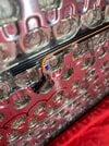
Measured modul 10 again. You were right! Orange cable is loose, cell 57. Is it absolutely excluded to soldering the cable to the battery? It seems like the plate is relatively thick and should not transfer that much heat directly to the cell? If not allowed to soldering, any tips how to connect the cable?

Is it possible that it was small condense and that made the isolation fault code? And this loose orange cable, cell 57, stopped me from charging the battery?
 

Attachments

  • DE0C21C5-4C04-4ADC-B230-B671A74F5EED.jpeg
    DE0C21C5-4C04-4ADC-B230-B671A74F5EED.jpeg
    433.5 KB · Views: 60
  • 1CA9D1F8-8F81-4526-8CB5-A6626614E115.jpeg
    1CA9D1F8-8F81-4526-8CB5-A6626614E115.jpeg
    694.5 KB · Views: 66
Upvote 0
Measured modul 10 again. You were right! Orange cable is loose, cell 57. Is it absolutely excluded to soldering the cable to the battery? It seems like the plate is relatively thick and should not transfer that much heat directly to the cell? If not allowed to soldering, any tips how to connect the cable?

Is it possible that it was small condense and that made the isolation fault code? And this loose orange cable, cell 57, stopped me from charging the battery?

Not sure how to weld.

I’ve seen some modules (maybe later ones?) use a orange flex cable rather than 3 individual wires and seem to use same ultrasonic weld as batteries between the plate to expose tabs on the flex cable.

Have a battery cell welder (just + - copper probes from a battery) for welding iPhone battery cells to its BMS. Welds aren’t very good compared to original. And it will spark. Don’t know if that puts any connected electronics at risk. Doesn’t damage iPhone BMS board.

Not sure how much heat sink is the electrode plate connected to many batteries. Heat and solder welding batteries are nearly impossible as the battery is such a big heat sink.
 
Upvote 0
Its not used with any other source.
My megger won't measure if it senses more than 30V...

Nice safety :)

But I guess need to be careful around LV circuits. I have experience fixing modern LV logic boards, one technique to finding LV circuit shorts is voltage injection into hot rails. Say 1v 1a on a rail then use a FLIR camera looking for the hot (shorted) components. Modern CPUs runs on 1v and can't handle much more than this so if inject say 5v on a rail that that CPU sits on, CPU will be dead.

I guess in general, meggers probably should only be deployed on HV rails WITH HV rail shutoff from its own HV source. For example, testing various HV rails in this car WITH first responder loop disconnected (battery pack contactors open)
 
Upvote 0
its not just safety its how it works
it sends an HV pulse n senses if any coming back ie leaking...
if u already have HV there u can't measure anything..
LV is easily isolated
HV needs better insulation, materials etc, since HV tends to arc/conduct thru certain less dialectic elements...
 
Upvote 0