Welcome to Tesla Motors Club
Discuss Tesla's Model S, Model 3, Model X, Model Y, Cybertruck, Roadster and More.
Register

Tesla Model S 2014 HV Battery issue

This site may earn commission on affiliate links.
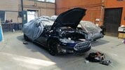
Hi, I have a Model S 2014 P85+

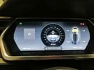
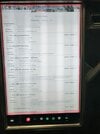
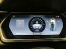
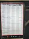
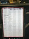
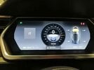
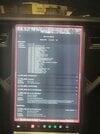
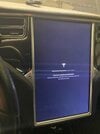
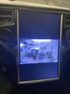
Last Monday I was driving it near from my house in Guatemala, but the car suddenly stoped with the warning: “Unable to drive, supply voltage too low”… I thought that would be a 12V battery failure, so, on my own, I replaced it for a new one. Yesterday, after installed it, the car woke up with 13 alerts on it, so I put it on “Service Mode” and take some pictures of the screen (please find them attached to this email),

2.jpeg


The more stressful alert for me was: BMS_f080_SW_Int_HV_Disconnect: the BMS has detected that the HV battery pack voltage differs from the sum of the brick voltages, making the HV battery unavailable for charging, driving or supporting the LV battery…

It look like is something is either not connected completely or properly from the battery, or maybe a problem with the HV battery itself?

Can somebody help me, where should I start to solve this problem?

Thanks a lot for your valuable help!

Juan Carlos
 

Attachments

  • 9.jpeg
    9.jpeg
    89.5 KB · Views: 406
  • 8.jpeg
    8.jpeg
    139.8 KB · Views: 317
  • 7.jpeg
    7.jpeg
    87.7 KB · Views: 297
  • 6.jpeg
    6.jpeg
    176.4 KB · Views: 288
  • 5.jpeg
    5.jpeg
    90.6 KB · Views: 279
  • 4.jpeg
    4.jpeg
    179.5 KB · Views: 277
  • 3.jpeg
    3.jpeg
    90.8 KB · Views: 273
  • 2.jpeg
    2.jpeg
    125.3 KB · Views: 314
  • 1.jpeg
    1.jpeg
    138.6 KB · Views: 456
Is it absolutely excluded to soldering the cable to the battery? It seems like the plate is relatively thick and should not transfer that much heat directly to the cell? If not allowed to soldering, any tips how to connect the cable?

EV Clinic showed a M3 single cell replacement and used a laser welder (towards end of video)

 
Upvote 0
Russian guys in this video put a rivet, cause they said something about not possible to solder to aluminum...


Nice, probably solder onto flex tab and route wire to rivot on side away from directly over the cells. And thats the video I saw with single flex cable rather than 3 wires. Must be later rev design change.

On soldering, only use leaded solder. lead-free will crack under vibration & thermal cycling (GPU failures). Fixed a few ECUs (Gen2 Rav4) and Instrument Panels (P2 Volvos) from cracked lead-free joints. NASA only send leaded solder spacecraft into space :)
 
Last edited:
  • Like
Reactions: brainhouston
Upvote 0
Measured modul 10 again. You were right! Orange cable is loose, cell 57.

voltage sensor wire contact looks completely detached. Did it completely break the weld after you touched it? If weld was broken before, I don't know how you could see slightly lower/higher voltage. Scan My Tesla developer explained to me if software reads 0v or 5v+, it will not display the brick.
 
Upvote 0
voltage sensor wire contact looks completely detached. Did it completely break the weld after you touched it? If weld was broken before, I don't know how you could see slightly lower/higher voltage. Scan My Tesla developer explained to me if software reads 0v or 5v+, it will not display the brick.
I would say that the cable was loose (like not welded). But it may be a combination, like almost loose :)
When measured at white contact I hade 1,2 V and started to drop to 0,8 V. Cable may have come loose when I measured module 10 the first time but I don’t think so. I know for sure that it was some pressure at the cable so it was against the plate. Not free in the air.
 
Upvote 0
Started to assemble modules in battery. I have now 16, 15, 14, 1, 2, 3 mounted. I do have some leakage voltage from 16, 15, 3, and 1.

Mainly leakage from module 16 and 3. When I measure between minus and chassis and minus and plus, it starts at around 3-4 voltage and starts to drop quickly. But it doesn’t drop to zero. It stays at 1,4V and 2,3V. Is this acceptable? I believe it must go down to zero to not have an isolation fault. Anyone that nows the limits?

All measurements with contact for contactors disassembled.
 

Attachments

  • 376C51D5-A33D-4254-B9DA-CC4D050AB677.jpeg
    376C51D5-A33D-4254-B9DA-CC4D050AB677.jpeg
    979.2 KB · Views: 100
  • 98CF389D-A99F-468C-B368-4DF7D931D156.jpeg
    98CF389D-A99F-468C-B368-4DF7D931D156.jpeg
    737.1 KB · Views: 52
Upvote 0
Any soldering of new voltage sensor wire to tab on yellow/gold flex might want to use conformal coating. Helping @mr_hyde figure out his BMB has a massively corroded cap while pack shows absolutely no sign of water ingress. This is just a guess but the pack appears not to be hermitically sealed (have a breather on top of hump, @brainhouston installed a moisture sensor post pack opening/repair and reports matching humidity to weather) I wonder if any exposed solder joint just gets attacked by humidity. In @mr_hyde BMB, conformal coating is likely rubbed off by the plastic cover over the top of the BMB touching the 2 tallest capacitors.

For reference, Rav4 EV and Mercedes (both invested in Tesla early) that uses the MS LDU and battery cells (I think modules are smaller due to lessor footprint) have serviceable desiccant cartridges in battery pack to mitigate small moisture content. Tesla obvious does not.
 
Last edited:
  • Informative
Reactions: Gtech
Upvote 0
I'm considering putting some desiccant bags in my pack before I seal it up. There is room in each module bay around the coolant connectors. I do recommend Richard looks at each BMB carefully for corrosion under magnifying glass or jeweler's visor. Now is the time to replace anything suspect.
 
Upvote 0
Thank you for tip. I have checked BMB cards and they looks alright.
I did like the russians and solderd the cable to a metal bleck and fasten it with a rivet. Extended an extra cable for BMS that I bought with a 2 meter cable. I have now connected the battery to the car. Still same failure codes as before. Cell imbalance at 24 mV :) Main display works now. Display worked fine for more than one hour with battery connected.

I decided now to make an upgrade of software (not in the service menu). After upgrade of software the back camera is the only thing I can see in my main display. According to many places on the internet a software upgrade can destroy the emmc. I believe this is what happened. Any ideas how to fix a dead emmc with a car without battery and on jacks? :) Will Tesla help me if I remove the screen my self?
 

Attachments

  • C519CBCD-E4EC-4EBB-B99D-176552E19EAC.jpeg
    C519CBCD-E4EC-4EBB-B99D-176552E19EAC.jpeg
    667.8 KB · Views: 43
  • AD0600EE-DEE4-47E7-9BF2-B7198C1FF691.jpeg
    AD0600EE-DEE4-47E7-9BF2-B7198C1FF691.jpeg
    377 KB · Views: 39
  • 92B3724E-105F-4AC0-B4BC-2055154B720C.jpeg
    92B3724E-105F-4AC0-B4BC-2055154B720C.jpeg
    402.8 KB · Views: 51
Last edited:
Upvote 0
Thank you for tip. I have checked BMB cards and they looks alright.
I did like the russians and solderd the cable to a metal bleck and fasten it with a rivet. Extended an extra cable for BMS that I bought with a 2 meter cable. I have now connected the battery to the car. Still same failure codes as before. Cell imbalance at 24 mV :) Main display works now. Display worked fine for more than one hour with battery connected.

I decided now to make an upgrade of software (not in the service menu). After upgrade of software the back camera is the only thing I can see in my main display. According to many places on the internet a software upgrade can destroy the emmc. I believe this is what happened. Any ideas how to fix a dead emmc with a car without battery and on jacks? :) Will Tesla help me if I remove the screen my self?

Maybe some connection problem since you didn't reinstall the battery pack and all the rapid-mate signals? I guess you probably already checked the wiring diagram to make your extension.

You had f107 code ( post #50 link ) Following thread post #84 #86 #98 show 2 different people need toolbox to clear BMS error flag after repair f107. I suspect @mr_hyde will need to do this as well.

 
Upvote 0
Maybe some connection problem since you didn't reinstall the battery pack and all the rapid-mate signals? I guess you probably already checked the wiring diagram to make your extension.

You had f107 code ( post #50 link ) Following thread post #84 #86 #98 show 2 different people need toolbox to clear BMS error flag after repair f107. I suspect @mr_hyde will need to do this as well.

I believe I have connected every cable as needed for rapid-mate signals. I did cut cable by cable when I extended it. And soldered it. I will ohm measure it to be sure.

Any ideas how I get access to toolbox?

Any ideas how to establish if emmc is broken? It seems to be very common and happen often when the car is updated with software.

My brother didn’t needed to reset with toolbox when his BMB card was broken. Just changed the BMB card. I believe he had f107. Voltage was high on one cell and low on one cell.

Also wk057 wrote that it should not be needed toolbox for f107? Maybe depending on software in the car? Post 77 and 78
Post in thread 'TESLA MODEL S stopped working... CAR MAY NOT RESTART'
TESLA MODEL S stopped working... CAR MAY NOT RESTART

TESLA MODEL S stopped working... CAR MAY NOT RESTART
 

Attachments

  • 9FFA098C-2FA6-44A8-BA67-76E5E5191CCE.jpeg
    9FFA098C-2FA6-44A8-BA67-76E5E5191CCE.jpeg
    741.8 KB · Views: 48
Last edited:
  • Helpful
Reactions: brainhouston
Upvote 0
Upvote 0
Upvote 0
Thanks! By the way, my brother had f017. So that’s maybe why it worked for him without toolbox. Is the only way to go online and pay to use toolbox? Any alternatives?

Don't know the answers to your question. I wonder if latest BMS reset feature in service mode will help clearing faults after repair


But unfortunately your MCU screen is not working now either to try this.
 
Upvote 0
Thank you for tip. I have checked BMB cards and they looks alright.
I did like the russians and solderd the cable to a metal bleck and fasten it with a rivet. Extended an extra cable for BMS that I bought with a 2 meter cable. I have now connected the battery to the car. Still same failure codes as before. Cell imbalance at 24 mV :) Main display works now. Display worked fine for more than one hour with battery connected.

I decided now to make an upgrade of software (not in the service menu). After upgrade of software the back camera is the only thing I can see in my main display. According to many places on the internet a software upgrade can destroy the emmc. I believe this is what happened. Any ideas how to fix a dead emmc with a car without battery and on jacks? :) Will Tesla help me if I remove the screen my self?

Maybe your MCU is not working well because 12v battery is low? Your HV battery pack doesn't connect the HV output to the car so 12v can not be charged by HV battery. Also if 12v was low when performing firmware upgrade, maybe that caused some problems?

But if you have 12v connected to external charger to keep charged up, then this is probably not the problem.
 
Upvote 0
Maybe your MCU is not working well because 12v battery is low? Your HV battery pack doesn't connect the HV output to the car so 12v can not be charged by HV battery. Also if 12v was low when performing firmware upgrade, maybe that caused some problems?

But if you have 12v connected to external charger to keep charged up, then this is probably not the problem.
I had one extra large 12V batteri connected and a 12V charger when I did the update to avoid 12V problem.

Thanks for the video. Seems like he struggled because the contactors were not open. Shouldn’t be a problem for me. I struggle to get my contactors closed🙂.

Anyhow. I contacted Tesla and I have made a service ticket. There is a campaign for emmc on my car. So now I hope a ranger can visit me and help to replace the emmc. Second option is to remove the screen and visit Tesla. Third option is to send the screen to Rumania or similar country to replace the emmc.

If the software got stuck I can not fix it anyway at the moment.
 
Upvote 0