Quite interesting about the 1/8" hole where coolant passes, I would think the amount of surface area to be cooled would be quite limited then and Tesla maybe just figures the shaft might warp after 150-200k miles vs. the coolant dillemma. I would opt for just doing a coolant delete and take the gamble over keeping the coolant flowing through the rotor. At least if the bearings fail the electronics won't get destroyed and maybe a $3-4k rebuild is in order every 100-150k miles worst case. I could live with that.With our solution you can do either NO rotor cooling (like the Rev U Tesla LDU), or as an option oil cooling can be added on. Our manifolds will be backwards compatible, so if you put it on without cooling and you change your mind, the cooling can be added on later (the drive unit would need to be removed from the vehicle to do so of course).
The cost of the base version (rotor cooling delete) will be $599 for the part, either available for DIY, or we can install it here at our shop. The labor should be somewhere in the ~4-5hr range to install it (drive unit needs to be removed from the vehicle to install). We still need to do some more validation and finalize parts sourcing for the optional oil cooling parts, but that will probably be in the ~$500 range, plus of course the extra labor to install. We would of course recommend a drain setup if utilizing the oil cooling for the rotor.
There is of course a risk of ATF leakage if there is a seal issue on the oil cooled option, but with oil there should be some significant advantages:
1. Lubricating properties of the oil "should" keep the seal from wearing out as quickly.
2. Oil is non-conductive, and non-corrosive, so IF it does leak, it shouldn't "destroy" the drive unit like coolant does.
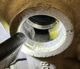
As far as disadvantages to not having cooling, it's hard to say for sure without long term data. Clearly Tesla has decided that will be their path forward, and one would like to think that they did some sort of serious validation to make this sort of change, but who knows... If I were to guess, the most likely downside would be a decreased lifespan of the rotor bearings, but I think that's a worthy tradeoff if it means the rest of the motor doesn't get destroyed by coolant intrusion. And honestly, the amount of cooling the rotor does get in the stock configuration is teeny tiny, as the main restriction is a ~1/8" hole where that circuit passes through the two case halves. As it is already, the rotor gets hot enough to discolor the steel laminations.
Welcome to Tesla Motors Club
Discuss Tesla's Model S, Model 3, Model X, Model Y, Cybertruck, Roadster and More.
Register
Install the app
How to install the app on iOS
You can install our site as a web app on your iOS device by utilizing the Add to Home Screen feature in Safari. Please see this thread for more details on this.
Note: This feature may not be available in some browsers.
-
Want to remove ads? Register an account and login to see fewer ads, and become a Supporting Member to remove almost all ads.
You are using an out of date browser. It may not display this or other websites correctly.
You should upgrade or use an alternative browser.
You should upgrade or use an alternative browser.
I am curious about their oil cooling option also. I'm not sure if Dexron is going to do any better with the seal. If it leaks, it will fill the inverter and Dexron is only dielectric when fresh.
There is of course a risk of ATF leakage if there is a seal issue on the oil cooled option, but with oil there should be some significant advantages:
1. Lubricating properties of the oil "should" keep the seal from wearing out as quickly.
2. Oil is non-conductive, and non-corrosive, so IF it does leak, it shouldn't "destroy" the drive unit like coolant does.
One note is the rotor's gearbox seal is handling similar surface speed as the coolant seal. Is a simple NBR V lipped seal and lubricated by ATF and keep ATF out of the motor chamber. Seems to work pretty well.
However, this seal is dealing with a non flooded gearbox chamber and without any pressure.
And honestly, the amount of cooling the rotor does get in the stock configuration is teeny tiny, as the main restriction is a ~1/8" hole where that circuit passes through the two case halves. As it is already, the rotor gets hot enough to discolor the steel laminations.
I've been also questioning the amount rotor is cooled due to this restriction (where the rotor cooling circuit output enters where the gearbox casing halve mate). At low PSI and this bottleneck, doesn't seem difficult to calculate how much heat can be transferred. But I'm no fluid dynamics engineer
i would think the seal would last much longer since the atf is a better lubricant than water and coolant. the dextron should have higher viscosity over coolant on an existing leaking seal, leading to less wear on the seal and less heat buildup on the shaft surface. atf seems like a win vs. coolant and maybe we get 250k out of a du. one can hope. a magnetic drain plug would be nice to have at the end of the tube to capture any metal debris like a typical transmission.Yes, there is a U revision for both the Sport and Base units, each in new or reman.
Nobody would know that yet. We really don't know what the "delete" version does since nobody has disassembled one...yet.
I am curious about their oil cooling option also. I'm not sure if Dexron is going to do any better with the seal. If it leaks, it will fill the inverter and Dexron is only dielectric when fresh.
an added advantage should be lower coolant temps on the inverter since the systems are then split and maybe lower ic temps leading to longer component life.
Last edited:
an added advantage should be lower coolant temps on the inverter since the systems are then split and maybe lower ic temps leading to longer component life.
I've seen some chatter on openinverter on split coolant loop (cool inverter and motor separately) People didn't like the fact that cooler running inverter gets cooled after the motor. Unfortunately can't find the thread atm.
the performance models are going to need to dissapate more heat on the fets, so cooling is probably more critical than base models.I've seen some chatter on openinverter on split coolant loop (cool inverter and motor separately) People didn't like the fact that cooler running inverter gets cooled after the motor. Unfortunately can't find the thread atm.
OhMYLRdy!
‘21 MYLR | WHITE/BLACK | 5 SEAT | TOW HITCH
First off this news is great, as there is finally a more permanent resolution to the LDU issue! I am curious, if one was to discover the seal was starting to leak, but no corrosive damage yet, is there something you could do to dry the electronics side out (spray in air, alcohol, parts cleaner, to evaporate the condensation) and then immediately install the new QC Adapter to prevent anymore damage moving forward?
First off this news is great, as there is finally a more permanent resolution to the LDU issue! I am curious, if one was to discover the seal was starting to leak, but no corrosive damage yet, is there something you could do to dry the electronics side out (spray in air, alcohol, parts cleaner, to evaporate the condensation) and then immediately install the new QC Adapter to prevent anymore damage moving forward?
Certainly... even with failures
- Coolant soaked low iso windings can be dried out
- Corroded inverter control board wiring harness can be changed with salvaged replacement
- Washed out rotor bearing grease can be repacked
NOTE the deadly HV danger when pulling and installing the LDU. Even experienced auto mechanic probably pause to think the first time putting a socket on the B+ B- bolts. Deadly danger is less common in ICE cars (except for caution around airbags)
OhMYLRdy!
‘21 MYLR | WHITE/BLACK | 5 SEAT | TOW HITCH
Thanks for the response, this will definitely be on my list of near future preventative maintenance as soon as it’s available. Just have to decide if I want to tackle it myself (I am very mechanically inclined), or schedule an appointment to drive from CO to CA to have it done. And yes point noted on the HV lines, definitely don’t want theCertainly... even with failures
Changing the manifold doesn't require pulling the reluctor wheel or motor end plate. But cleaning the motor interior does which requires some tooling/work. Coolant leak could also have rusted the rotor bearing to the bore and make it hard for the rotor to come out.
- Coolant soaked low iso windings can be dried out
- Corroded inverter control board wiring harness can be changed with salvaged replacement
- Washed out rotor bearing grease can be repacked
NOTE the deadly HV danger when pulling and installing the LDU. Even experienced auto mechanic probably pause to think the first time putting a socket on the B+ B- bolts. Deadly danger is less common in ICE cars (except for caution around airbags)
Hello. thanks for the detailed post. Could you please share the information whether you managed to install this bypass or not?J-B Weld Water Weld it awesome because you can shape it as you apply the product. Waiting for it to set up and then will sand it flat.
blodg1
Member
Yes. I have installed two of them.Hello. thanks for the detailed post. Could you please share the information whether you managed to install this bypass or not?
Planning to install bypass to my car - TMS P85D. Have you experienced any issues with the drive unit overheating?Yes. I have installed two of them.
blodg1
Member
Wouldn't know, there is no sensor in the rotor. Stator hasn't shown any problems.Planning to install bypass to my car - TMS P85D. Have you experienced any issues with the drive unit overheating?
Here are some thoughts on how to gather rotor temperature before/after coolant delete manifold
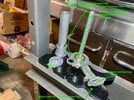
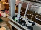
A little more progress this morning. Home Depot only sells one aluminum tube stock and it happens to be the exact size I needed. Very tight press fit. Next step will be filling in the gaps with JB Weld.
Any idea how much gap between the rotor shaft and the sleeved in 1/2" OD Aluminum Everbilt tubing + JB Weld? Not very much space in that gap and the shaft can push outward slightly with the bevel washer spring on the outer rotor bearing.
Another alternative idea is to cap the end of manifold coolant tube. Then run a bypass outside of the manifold (T the coolant inlet rubber hose feeding the manifold, cut the exit tube from the manifold, connect hose between these 2)
blodg1
Member
The tube walls are thick enough that I wasn't too concerned about clearance. On the second one I used a large socket in the press to clearance the portion of the tube that extended past the machined area the old cooling tube was mounted. Unfortunately I failed to take a photo.Any idea how much gap between the rotor shaft and the sleeved in 1/2" OD Aluminum Everbilt tubing + JB Weld? Not very much space in that gap and the shaft can push outward slightly with the bevel washer spring on the outer rotor bearing.
On the second one I used a large socket in the press to clearance the portion of the tube that extended past the machined area the old cooling tube was mounted. Unfortunately I failed to take a photo.
Sounds like you bent/flatten the 1/2" OD tube slightly after install to provide more clearance?
blodg1
Member
Correct. Appeared to be less than 1mm.Sounds like you bent/flatten the 1/2" OD tube slightly after install to provide more clearance?
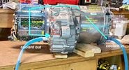
Brain storming with @mr_hyde and consulted with @asavage with various coolant delete bypass modification to find something simple to make and minimal existing part destruction. Here is a proposal
Current coolant channel is
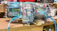
A simple solution can be
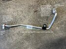
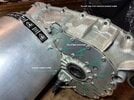
The inverter coolant exit at the bottom of heat exchanger (see pic below) located close to the LDU coolant outlet also on the bottom results in likely air pockets towards top of heat exchanger. This require vacuum fill of coolant to eliminate. Ideally, LDU coolant output at top of the heat exchanger would be much better. But realistically likely not much of an issue. Gearbox metal material itself carries heat. ATF sloshing around inside caries heat gravitates towards bottom where majority of heat exchange with coolant take place. Furthermore, gearbox heat is likely far lower than the stator + inverter heat.
Inverter coolant exit to gearbox heat exchanger and fly over tube dumping into heat exchanger was identified in the following video. Don't have a pic of the heat exchanger cover removed.
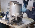
The last video shows the guy's left thumb near where the fly over tube enters the gearbox half with the heat exchanger. As he rotates it over, a triangular outlet shows the coolant just dumps to into the top of the heat exchanger.
Current coolant channel is
- inlet -> Y split to stator and rotor. passage is much bigger towards the stator.
- stator -> inverter -> gearbox heat exchanger -> outlet
- rotor -> heat exchanger (via fly over tube) -> outlet

A simple solution can be
- cap off manifold tube to block coolant from entering inside the rotor
- block off manifold exit port with alum plate + mounting hole + RTV
- ideally have a billet (with o-ring/seat) blocking the gearbox port where fly over tube enters to prevent heat exchanger coolant from backing out. Or just a cylinder with an o-ring seat + blocking plate with bolt hole. Can even glue it together


The inverter coolant exit at the bottom of heat exchanger (see pic below) located close to the LDU coolant outlet also on the bottom results in likely air pockets towards top of heat exchanger. This require vacuum fill of coolant to eliminate. Ideally, LDU coolant output at top of the heat exchanger would be much better. But realistically likely not much of an issue. Gearbox metal material itself carries heat. ATF sloshing around inside caries heat gravitates towards bottom where majority of heat exchange with coolant take place. Furthermore, gearbox heat is likely far lower than the stator + inverter heat.
Inverter coolant exit to gearbox heat exchanger and fly over tube dumping into heat exchanger was identified in the following video. Don't have a pic of the heat exchanger cover removed.


The last video shows the guy's left thumb near where the fly over tube enters the gearbox half with the heat exchanger. As he rotates it over, a triangular outlet shows the coolant just dumps to into the top of the heat exchanger.
Last edited:
We looked over everything we can glean from pictures and it looks like doing the 'two plug' method should work fine. What are we missing?A simple solution can be
- cap off manifold tube to block coolant from entering inside the rotor
- block off manifold exit port with alum plate + mounting hole + RTV
- ideally have a billet (with o-ring/seat) blocking the gearbox port where fly over tube enters to prevent heat exchanger coolant from backing out.
Similar threads
- Replies
- 19
- Views
- 8K
- Replies
- 55
- Views
- 19K


