


Welcome to Tesla Motors Club
Discuss Tesla's Model S, Model 3, Model X, Model Y, Cybertruck, Roadster and More.
Register
Install the app
How to install the app on iOS
You can install our site as a web app on your iOS device by utilizing the Add to Home Screen feature in Safari. Please see this thread for more details on this.
Note: This feature may not be available in some browsers.
-
Want to remove ads? Register an account and login to see fewer ads, and become a Supporting Member to remove almost all ads.
You are using an out of date browser. It may not display this or other websites correctly.
You should upgrade or use an alternative browser.
You should upgrade or use an alternative browser.
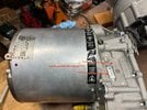
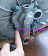
Im trying to do the bypass as easy as possible by not removing the LDU. I drilled a hole on the trunk Bec there is no space around the LDU to get to the top coolant line. With the hole, the top coolant line can be easily disconnected and be connected to a line that will be connected to the tee fitting.
Interesting access method! Luckily LDU HV cables run along the other (passenger) side ")
I know the motivation to not remove the LDU. But couple of thoughts
Not too hard with 2 floor jacks, 8' 4x4 strong wooden beam and a cheap motorcycle jack
See post #91 towards the bottom "Jacking Up the Rear to Put on Stand" AND post #10 ) Followed by a cherry picker to pull LDU out of subframe post #15. All the LDU's weight is on the stator side so center of gravity on the pull bias that direction to avoid tilting the LDU on removal (not much space with wrap around subframe and likely easy to break the weak LDU aluminum mount welds on the subframe)
Running the PTFE seal dry with a hotter rotor might not be a good idea
Reading the seal design literature. A key factor to consider is frictional heat. Few key factors
Furthermore, on the dry side of the seal lip, unavoidable slight leak will crystalize coolant into silicate solid particles which probably act like sandpaper against the shaft.
Multi lipped seals do have a mostly dry lip on the dry facing side. But its mated against a shaft surface that is getting cooled with coolant.
====
About to pull my LDU for the 3rd time this coming week and thinking about manifold mod. A few thoughts

Also thought about tap inlet with T. Need to worry about reduced flow rate with a narrowing passage at the T. Maybe not much and is okay.
Thinking about drilling a hole on side of the manifold neck to access the coolant tunnel that runs up the neck. Manifold is not structural here so can make the drilled hole quite large. Large enough to consider the following
Even not routing the coolant into the fly over tube maybe okay. Entry to gearbox is 5mm diameter hole. Once inside, just combine with majority of the coolant that went through stator casing->inverter at the gearbox heat exchanger before existing the LDU ( post #139 )
Anyway, plugging the rotor coolant tunnel is the main mod challenge.
I know the motivation to not remove the LDU. But couple of thoughts
Not too hard with 2 floor jacks, 8' 4x4 strong wooden beam and a cheap motorcycle jack
See post #91 towards the bottom "Jacking Up the Rear to Put on Stand" AND post #10 ) Followed by a cherry picker to pull LDU out of subframe post #15. All the LDU's weight is on the stator side so center of gravity on the pull bias that direction to avoid tilting the LDU on removal (not much space with wrap around subframe and likely easy to break the weak LDU aluminum mount welds on the subframe)
Running the PTFE seal dry with a hotter rotor might not be a good idea
Reading the seal design literature. A key factor to consider is frictional heat. Few key factors
- Surface speeds (m/s) = shaft diameter x rotation speed. Most advanced rubber seals handle up to like 5-10 m/s. PTFE can do higher like 30 m/s ( SKF )
- Rotor's 30mm diameter shaft at say 7k RPM (~70mph) = 2 x pi x 15mm / 1000 x 7000RPM / 60s/min = 10m/s
- Contact cross section of the seal. Narrower (V lipped rubber seal contact ~= 0.2mm) = higher heat density. Luckily Lipped PTFE seal contact region is like 2mm cross section for a lower heat density. This is a huge factor in why they can tolerate higher surface speeds
Furthermore, on the dry side of the seal lip, unavoidable slight leak will crystalize coolant into silicate solid particles which probably act like sandpaper against the shaft.
Multi lipped seals do have a mostly dry lip on the dry facing side. But its mated against a shaft surface that is getting cooled with coolant.
====
About to pull my LDU for the 3rd time this coming week and thinking about manifold mod. A few thoughts
Also thought about tap inlet with T. Need to worry about reduced flow rate with a narrowing passage at the T. Maybe not much and is okay.
Thinking about drilling a hole on side of the manifold neck to access the coolant tunnel that runs up the neck. Manifold is not structural here so can make the drilled hole quite large. Large enough to consider the following
- Inject RTV into the tunnel, maybe seal the inlet side with JB Weld so RTV can get pressured up against a stop and squeeze into any tiny gaps at this stop.
- Offers opportunity to tap a bypass coolant channel and run it up to the fly over tube
- Or just insert a cylinder plug with RTV to seal the tunnel.
Even not routing the coolant into the fly over tube maybe okay. Entry to gearbox is 5mm diameter hole. Once inside, just combine with majority of the coolant that went through stator casing->inverter at the gearbox heat exchanger before existing the LDU ( post #139 )
Anyway, plugging the rotor coolant tunnel is the main mod challenge.
Thank you howardc64 for the wealth of knowledge you have with the LDU. I've been reading your posts nonstop in the forum, very informative. I still have so much to read.Interesting access method! Luckily LDU HV cables run along the other (passenger) side
I know the motivation to not remove the LDU. But couple of thoughts
Not too hard with 2 floor jacks, 8' 4x4 strong wooden beam and a cheap motorcycle jack
See post #91 towards the bottom "Jacking Up the Rear to Put on Stand" AND post #10 ) Followed by a cherry picker to pull LDU out of subframe post #15. All the LDU's weight is on the stator side so center of gravity on the pull bias that direction to avoid tilting the LDU on removal (not much space with wrap around subframe and likely easy to break the weak LDU aluminum mount welds on the subframe)
Running the PTFE seal dry with a hotter rotor might not be a good idea
Reading the seal design literature. A key factor to consider is frictional heat. Few key factors
This include seal contact surface getting cooled by circulating coolant and hydroplaning over lubricating media in oil media. Without circulating media, and no shaft cooling, lips are probably going to burn up. PTFE seal material is like really hard plastic. No idea what happens to them getting cooked.
- Surface speeds (m/s) = shaft diameter x rotation speed. Most advanced rubber seals handle up to like 5-10 m/s. PTFE can do higher like 30 m/s ( SKF )
- Rotor's 30mm diameter shaft at say 7k RPM (~70mph) = 2 x pi x 15mm / 1000 x 7000RPM / 60s/min = 10m/s
- Contact cross section of the seal. Narrower (V lipped rubber seal contact ~= 0.2mm) = higher heat density. Luckily Lipped PTFE seal contact region is like 2mm cross section for a lower heat density. This is a huge factor in why they can tolerate higher surface speeds
Furthermore, on the dry side of the seal lip, unavoidable slight leak will crystalize coolant into silicate solid particles which probably act like sandpaper against the shaft.
Multi lipped seals do have a mostly dry lip on the dry facing side. But its mated against a shaft surface that is getting cooled with coolant.
====
About to pull my LDU for the 3rd time this coming week and thinking about manifold mod. A few thoughts
View attachment 1013125
Also thought about tap inlet with T. Need to worry about reduced flow rate with a narrowing passage at the T. Maybe not much and is okay.
Thinking about drilling a hole on side of the manifold neck to access the coolant tunnel that runs up the neck. Manifold is not structural here so can make the drilled hole quite large. Large enough to consider the following
Connecting coolant flow to the fly over tube have lots of options and should be much easier. Can cut and connect to this tube towards the gear box. Can Tee it. RTV a blocking plate can seal the manifold coolant exit and any fly over tube back flowing into the manifold.
- Inject RTV into the tunnel, maybe seal the inlet side with JB Weld so RTV can get pressured up against a stop and squeeze into any tiny gaps at this stop.
- Offers opportunity to tap a bypass coolant channel and run it up to the fly over tube
- Or just insert a cylinder plug with RTV to seal the tunnel.
Even not routing the coolant into the fly over tube maybe okay. Entry to gearbox is 5mm diameter hole. Once inside, just combine with majority of the coolant that went through stator casing->inverter at the gearbox heat exchanger before existing the LDU ( post #139 )
Anyway, plugging the rotor coolant tunnel is the main mod challenge.
I didn't think about the dry PTFE seal and really appreciate for pointing that out. I think what Im going to do now is to put a zerk fitting on the cover that I will putting where the fly over tube is. I'll inject grease until I can see on the speed sensor hole. Can you suggest a good grease that is optimal to use with the PTFE seal?
Drilling a hole in the manifold neck is a good idea I will do that. I bought a extra fly over tube so I can mock up a connection for it the tee.
Forgot to mention HV SAFETY. Definitely disconnect the HV first responder loop even if most of cutting / poking around is away from the inverter. The pair of B+ B- HV cable to the LDU probably runs about 1-2 feet away from where you got the hole.
===
On 2nd thought, leaving the PTFE seal in and running it dry with coolant delete "could" be fine. Just have no way of knowing.
PTFE seal works completely different from standard advanced rubber seals. PTFE is basically teflon tape material you use in plumbing but obviously much thicker. A block of it probably feels like really slippery hard plastic. The way a PTFE seals works on a rotational shaft is to transfer a thin layer of PTFE material onto the shaft when it first beds in, then PTFE seal is sliding against this transferred material for ultra low friction.
To transfer this material, shaft surface need very microscopic imperfections (defined by a roughness spec) If shaft is polish mirror smooth (can't see the difference with micron level spec) this material transfer is incomplete and seal leaks quickly.
So clearly, on a triple lip seal, the dry side facing dry lip is not getting cooled by coolant. But spinning on a cooler rotor shaft compared to a coolant deleted shaft. No one has design analysis info on how much hotter will the shaft be and what can the PTFE seal tolerate.
Just a slight more detail on PTFE seals is they are usually blended with additive particles. Virgin PTFE wears away quickly. Microscopic additive particles are blended in to act like a pier pillar against the shaft's metal surface to limit the PTFE material wear rate. The additive particle hardness then need to be relative to the hardness of the shaft. Too hard seal compared to shaft = wear shaft. Too soft seal compared to shaft = fast seal wear. This is why Tesla's reman LDU failed so quickly. They don't seem to bother reconditioning that shaft back to spec (which might require electroplating + polishing) In retrospec, requiring such tight tolerance might not have been a good idea and incomplete reman effort reduces longevity significantly. We are reading people getting reman LDU and leak bad enough to damage the LDU just a few months later. I'm guessing reman 1x is already bad enough, imagine getting a multiple remanned LDU with rotor shaft never reconditioned... Yikes on such high precision seal requirement.
Anyhow, hope this helps. Just thought hey... why can't the PTFE seal live dry and in hotter climate? Dry lip already does just maybe not as hot before delete.
BTW, that dry lip is called an excluder lip. Its to exclude debris from entering and interfering the wet side facing seals.
Finally on grease, every single PTFE rotational seal information I've read says mount seal on a completely clean surface without grease. So everyone include all LDU rebuilders I know do it this way. Tesla DOES put grease on install. Maybe its to help seal's blind installation without folding the excluder lip (really tricky, most never handled PTFE seal before will fold it and ruin it from start) This is why first time pulling speed sensor will always have oily gunk on there. We don't know why Tesla does this as It counters everything we read about PTFE and every rebuilder's practice. Based on my above explanation on how PTFE seal transfers microscopically thin layer to form its own sealing surface gap. It kind of make sense don't want any foreign material to contaminate this transfer. Anyway, I don't understand why Tesla put in grease. So for grease, you are on your own to make decision. I can only offer observation and literature guidance.
You definitely don't want to pack grease on the dry side of chamber until it oozes out of speed sensor hole. There are a bunch of stuff in there all spinning at high speeds. Reluctor wheels teeth spins in there at 6-7k RPM during highway speeds. Ceramic bearings and bevel spring washers are all in the dry side of the chamber fully exposed to whatever grease you pack in there. Ceramic bearings also have its own $$$$ special grease inside of its rubberized seal (not super tight seal, just a rubberized washer with lip over some bearing race grooves.
Last edited:
OhMYLRdy!
‘21 MYLR | WHITE/BLACK | 5 SEAT | TOW HITCH
As I'm looking at the hole you cut in the trunk to access the top bolt of the manifold pipe, I can't help but wonder if one could cut a rectangular hole to gain access to the whole manifold to unbolt from above and bolt on the updated QC Charge manifold without removing the LDU? Then maybe 3D print a cover to reinstall over the rectangle hole?View attachment 1012934View attachment 1012933
Im trying to do the bypass as easy as possible by not removing the LDU. I drilled a hole on the trunk Bec there is no space around the LDU to get to the top coolant line. With the hole, the top coolant line can be easily disconnected and be connected to a line that will be connected to the tee fitting.
Pulling the LDU and maybe 3rd time is a charm
First rebuild rusted under triple lip PTFE seal. Reman LDU rotor shaft likely had inherited compromised rust proofing in Tesla reman.
2nd rebuild leaked in 500 miles. Chose a FKM (more advanced than traditional NBR rubber) seal with 2 others reporting good result with SKF speedi-sleeve. No success in my effort which is the expected result (seal not designed to handle this level of surface speeds)
Pulling 3rd time to do coolant delete. Leaving couple of notes on the pull and diagnostic testing
Lifting Height and Pulling LDU


Testing LDU in Car Isolating Noises
A lot of things rotating (LDU's internal gears, axle shafts with its 2 CVs, 2 rotors with 4 caliper pads dragging) makes it difficult to isolate rotation noises. Can do the following isolation process

Eventually found a per final drive revolution click sound in the gearbox. Will open the gearbox and inspect the final drive gear+bearings carefully on this pull.
I guess onto coolant manifold delete + finding the per final drive revolution click sound. With @mr_hyde help, robably do thorough bearing bore depth + shim measurements like suppose to do when rebuilding a gearbox.
First rebuild rusted under triple lip PTFE seal. Reman LDU rotor shaft likely had inherited compromised rust proofing in Tesla reman.
2nd rebuild leaked in 500 miles. Chose a FKM (more advanced than traditional NBR rubber) seal with 2 others reporting good result with SKF speedi-sleeve. No success in my effort which is the expected result (seal not designed to handle this level of surface speeds)
Pulling 3rd time to do coolant delete. Leaving couple of notes on the pull and diagnostic testing
Lifting Height and Pulling LDU
- @mr_hyde brought his smaller Quick Jack with an additional longer extension. Non air suspension car. Floor jack raised rear subframe just a couple of inches to clear and insert the Quick Jack (prob depending on garage leveling) Floor to bottom of Tesla lift pad = 20"
- LDU in subframe on typical 500lb scissor lift table (Harbor Freight etc) fully lowered is 24" from floor to highest spot
- Rear underbody + cover shield behind the LDU+subframe is 21" from floor
- Pulled the cart + LDU out sideways through the big wheel well openning. Front wheels on these lower end carts don't articulate (everyone I've seen) But hard plastic rubber wheel sled side ways with a little muscle on the smooth garage floor. A stripe of carpet + furniture mover sliders under front cart wheel would make it quite easy.
Testing LDU in Car Isolating Noises
A lot of things rotating (LDU's internal gears, axle shafts with its 2 CVs, 2 rotors with 4 caliper pads dragging) makes it difficult to isolate rotation noises. Can do the following isolation process
- Drive units can be driven at low speed in dynotest mode with tires off the ground. Can't go faster so car has some smarts.
- Drive LDU with brake caliper removed but maintain hydraulic connection. Insert slightly thicker object than disc rotor (~28mm in my case, used jack stand's vertical stand) Ziptie and bungie onto rear springs out of the way.
- Drive LDU with parking brake removed from rotor but remain electronically connected. 2 bolt (very tight on removal / install, easy to not bottom out on reinstall) disconnects the parking brake caliper. Putting car in R,D,N releases the parking brake to remove it. To back off parking brake pads, need to separate the motor and gear box (3 T20? Torx bolts) and turn the gear manually ( youtube video removed rotor+parking brake from car so much easier). Same slightly thicker than disc rotor object ziptied and place it somewhere away from things that rotate when LDU is turning. Parking brake remain connected to the car so it doesn't complain and allow driving the LDU.
- Drive LDU with axle removed : Drain ATF, will only do short low speed test so no damage. Hub require moving all the visible link+arm outer bolts and nuts AND 1 speed sensor. Car doesn't complain driving LDU in dynotest mode with speed sensor removed
Eventually found a per final drive revolution click sound in the gearbox. Will open the gearbox and inspect the final drive gear+bearings carefully on this pull.
I guess onto coolant manifold delete + finding the per final drive revolution click sound. With @mr_hyde help, robably do thorough bearing bore depth + shim measurements like suppose to do when rebuilding a gearbox.
Last edited:
OhMYLRdy!
‘21 MYLR | WHITE/BLACK | 5 SEAT | TOW HITCH
My QC Charge Coolant delete manifold showed up today! Just waiting for them to release the DIY video before deciding on if I’ll tackle it myself or take it to them.


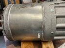
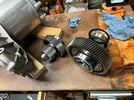
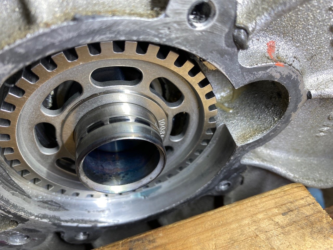
This is my idea for a coolant delete. I obtai
 ned a second hand manifold and cut off the rotor tube. I belt sanded the stub of it to below the level of the circlip. I made an alumin
 ium cup on a mini lathe and pressed it in. The depth of the centre is 12mm. I hope that is deep enough.
I'm not planning to fit it until I detect coolant on the speed sensor.


I'm not planning to fit it until I detect coolant on the speed sensor.
brainhouston
Active Member
This is my idea for a coolant delete. I obtaiThe depth of the centre is 12mm. I hope that is deep enough.
Might need 13-14mm deep ( post #57 pdf )Rotor also sits on a bevel washer spring so theoretically can push out a little (< 0.5mm?) on high speed right hand motion.
But yes, would be nice just to have a stainless cap in this shape where seal use to go.
Small custom PTFE seal makers will make ~5 seals in stainless cages for $500. I'd imagine even cheaper just to press cages in the right shape.
Thanks for the advice Howard. Now I have an excuse to buy a small mill. The base of my cup is about 6mm thick, so I'll remove another 3.Might need 13-14mm deep ( post #57 pdf )Rotor also sits on a bevel washer spring so theoretically can push out a little (< 0.5mm?) on high speed right hand motion.
But yes, would be nice just to have a stainless cap in this shape where seal use to go.
Small custom PTFE seal makers will make ~5 seals in stainless cages for $500. I'd imagine even cheaper just to press cages in the right shape.
Thanks for the advice Howard. Now I have an excuse to buy a small mill. The base of my cup is about 6mm thick, so I'll remove another 3.
That’s great to know you have 12+6mm depth to use.
Post #106 shows fairly clean bore with tube pressed out. So 2 pressed on stainless caps with RTV in the right shape would work great.
I’ll reach out to Ceimin triple lip seal maker to see if they can provide stainless steel caps. They are small Chinese ptfe seal maker and every rebuilder I know use their triple lip ptfe seal for LDU rebuild. Pressing stainless caps should be trivial for them.
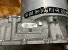
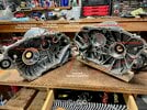
Looks like the 2 halves of my reman LDU gearbox is made 4 year apart.
Here is the history of battling a whine in this gearbox for 7 years
Discussed with @asavage on measure axial alignment of the 3 shafts. Need expensive jigs. Basically a master jig for each half of gearbox to measure the other half that is mass produced. Presumably desirable if mix gearbox halves spanning a 4 year gap in reman.
I've read experienced gearbox rebuilders talks about shims and motorcycle gearbox guys arguing about matched or unmatched gearbox halves.
In any case, just a guess but perhaps the mismatched case half 4 years apart in manufacturing could be the cause of my whine and changed when the primary counter bore bearing was and was not glued down.
As for why mix gearbox halves. Stator is glued into its half rather than bolted on like other EV motors. So I'd imagine when stator is ruined by coolant, that half of the gearbox is lost as well ( although EV Clinic seems to know how to exchange it link )
Anyhow, just conjectures without any Tesla reman process data. Stripped inverter mounting bolt holes and not refinishing rotor shaft for new seal doesn't inspire confidence.
One more trend this is illustrating is lack of design for rebuilding trend which successive battery generations are exhibiting.
- LDU Label says T13...R1
- inverter 1/2 of the case has printed T17...
Here is the history of battling a whine in this gearbox for 7 years
- Got a regen whine when first got this this reman in 17/18. Unfortunately SCs started denying hearing noises + replacing LDUs soon after. SC checked and said no action on the noise every year until past warranty.
- My first rebuild effort late 22 (fix a leaky seal)
- Found primary shaft counter bore bearing's outer race spun against the bore ( pic in post #47 )
- Replaced + bearing gluing lock tite against the bore. Whine changed to forward motion now and less regen.
- 2nd rebuild effort (replaced rusted shaft under PTFE seal) Replaced primary shaft bearings, lock tite down the primary counter bore bearing against bore. Whine same as after 1st rebuild.
Discussed with @asavage on measure axial alignment of the 3 shafts. Need expensive jigs. Basically a master jig for each half of gearbox to measure the other half that is mass produced. Presumably desirable if mix gearbox halves spanning a 4 year gap in reman.
I've read experienced gearbox rebuilders talks about shims and motorcycle gearbox guys arguing about matched or unmatched gearbox halves.
In any case, just a guess but perhaps the mismatched case half 4 years apart in manufacturing could be the cause of my whine and changed when the primary counter bore bearing was and was not glued down.
As for why mix gearbox halves. Stator is glued into its half rather than bolted on like other EV motors. So I'd imagine when stator is ruined by coolant, that half of the gearbox is lost as well ( although EV Clinic seems to know how to exchange it link )
Anyhow, just conjectures without any Tesla reman process data. Stripped inverter mounting bolt holes and not refinishing rotor shaft for new seal doesn't inspire confidence.
One more trend this is illustrating is lack of design for rebuilding trend which successive battery generations are exhibiting.
Attachments
nemisonic
New Member
Z3ds:View attachment 1012934View attachment 1012933
Im trying to do the bypass as easy as possible by not removing the LDU. I drilled a hole on the trunk Bec there is no space around the LDU to get to the top coolant line. With the hole, the top coolant line can be easily disconnected and be connected to a line that will be connected to the tee fitting.
Have you been able to prototype the on-vehicle fix? Do you have any tips/tricks or parts list to share? I've been under the vehicle for a speed-sensor check and with your tip to cut access hole in body, it looks like this would be do-able after disconnecting the HV first responder's loop, and safely using heavy-duty jack-stands.
I am familiar with the QC-Charge part, and have done serious work on vehicles DIY like the LDU removal- but on ICE transmissions and transfer cases for 4x4s. That being said, I would much prefer to try this "on vehicle" fix because of how PITA factor is on this level of DIY (and $7k to Tesla SC is crummy) and we no longer live near Carlsbad, CA to ask QC Charge to do it (unless someone knows a partner in New England?).
I am already burned by a $16k battery on a 50k mile vehicle, wonder if it is worthwhile trying this fix vs. dumping the lemon.
Thanks!
Hi nemisonic,Z3ds:
Have you been able to prototype the on-vehicle fix? Do you have any tips/tricks or parts list to share? I've been under the vehicle for a speed-sensor check and with your tip to cut access hole in body, it looks like this would be do-able after disconnecting the HV first responder's loop, and safely using heavy-duty jack-stands.
I am familiar with the QC-Charge part, and have done serious work on vehicles DIY like the LDU removal- but on ICE transmissions and transfer cases for 4x4s. That being said, I would much prefer to try this "on vehicle" fix because of how PITA factor is on this level of DIY (and $7k to Tesla SC is crummy) and we no longer live near Carlsbad, CA to ask QC Charge to do it (unless someone knows a partner in New England?).
I am already burned by a $16k battery on a 50k mile vehicle, wonder if it is worthwhile trying this fix vs. dumping the lemon.
Thanks!
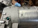
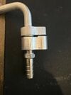
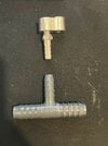
I have just finished prototyping the connector for the top coolant tube. I know there’s minimal coolant going up there but Im trying to emulate as much as possible what tesla did with their coolant delete design. I used a block off ac kit for the chevy suv. They are like $11 on amazon. I drilled and tapped to accept a 1/4npt hose barb. I also enlarged the hole for the top coolant tube to 13mm.
Im going to do the mod to my car next week.
Im in the early stage of developing a coolant delete kit for people who dont have the equipment of dropping the LDU. Basically just cut the manifold and cut a hole in the trunk. This is all assuming that the rotor wont overheat without cooling.
Attachments

This solution might be a little extreme
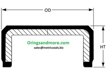
If the portion of the rotor shaft for the seal is cut off (I'll call it the snout, probably no balance problems being in the center of the 70lb rotor, if examine the rotor closely, all the weight drilling marks to balance the rotor is towards the outer diameter just like a car wheel) then a simple 55mm plug cap like this would work with the coolant rotor tube removed
 www.oringsandmore.com
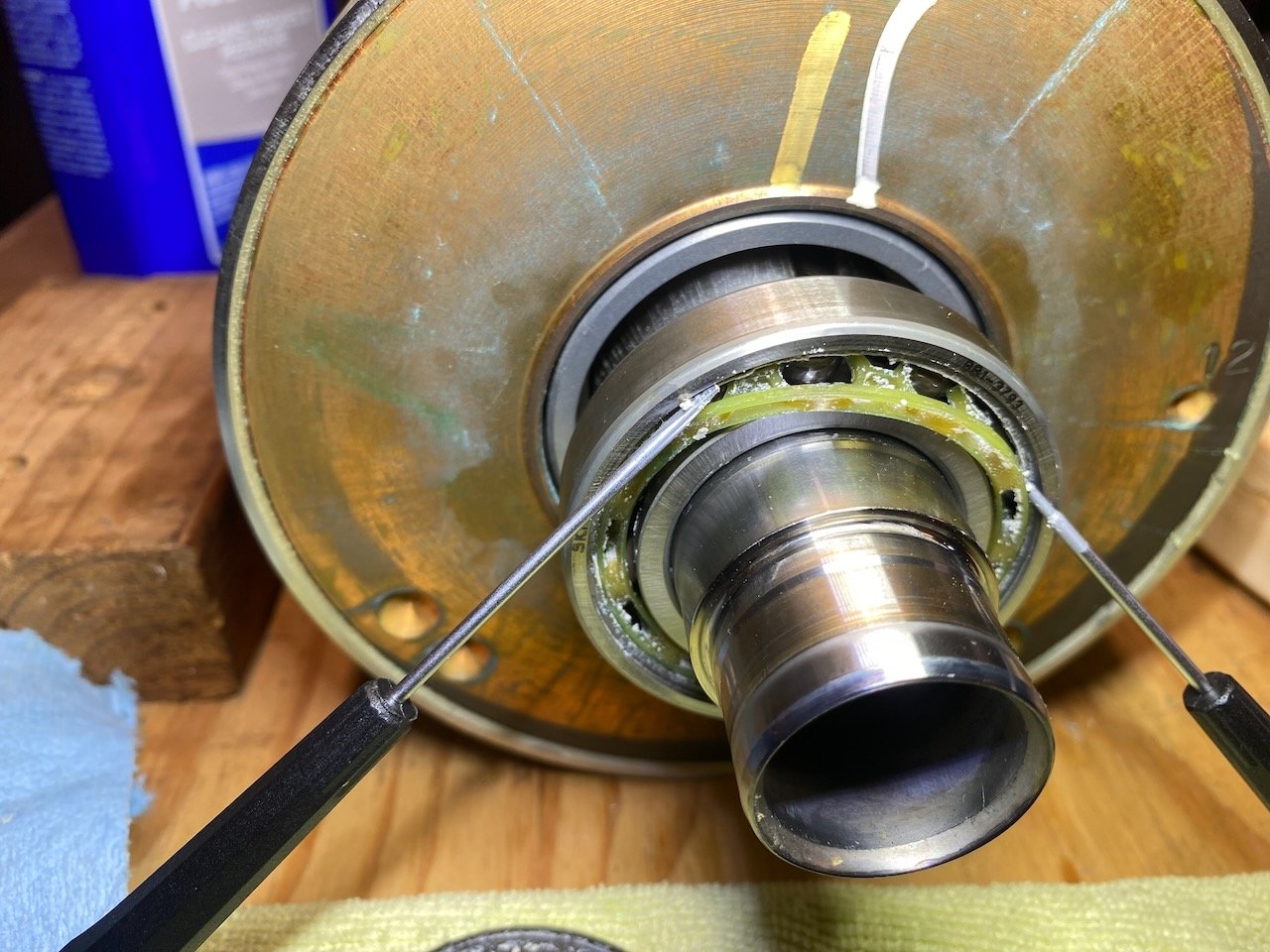
If the rotor tube is pressed out, then need to find a solution to close the outside hole. Haven't measured its diameter and hole surface also scored axially from pressed in tube.
But cutting off the snout = rotor can never return to liquid (coolant/oil) cooled solution.
Anyway, still searching for the cap with the right dimension without requiring cutting off snout. Something like this

If the portion of the rotor shaft for the seal is cut off (I'll call it the snout, probably no balance problems being in the center of the 70lb rotor, if examine the rotor closely, all the weight drilling marks to balance the rotor is towards the outer diameter just like a car wheel) then a simple 55mm plug cap like this would work with the coolant rotor tube removed
55mm OD x 10.0mm HT End Cap Seal Price for 1 pc
<p><font color="#a52a2a" size="4" face="Georgia">1-3/4" ID x 2-1/8" OD x 3/8 Height x 3/16 CS Thickness-Price for 1 pc</font></p>
www.oringsandmore.com
If the rotor tube is pressed out, then need to find a solution to close the outside hole. Haven't measured its diameter and hole surface also scored axially from pressed in tube.
But cutting off the snout = rotor can never return to liquid (coolant/oil) cooled solution.
Anyway, still searching for the cap with the right dimension without requiring cutting off snout. Something like this
Last edited:
Did a bunch of measurements while considering speedi sleeve shaft surface reconditioning and needed to figure out where the seal lips will land.
Also calculated how deep of a cup is necessary for those looking to remove coolant tube and cap the seal bore. Looks like need to go about 15mm deep from seal bore to clear the rotor shaft comfortably by ~2mm (before any rotor axial movement per bevel washer spring (maybe max 0.5mm)) and still 4mm to the shoulder below circlip for coolant passage and cup thickness. Page 1 of attached PDF
Also calculated how deep of a cup is necessary for those looking to remove coolant tube and cap the seal bore. Looks like need to go about 15mm deep from seal bore to clear the rotor shaft comfortably by ~2mm (before any rotor axial movement per bevel washer spring (maybe max 0.5mm)) and still 4mm to the shoulder below circlip for coolant passage and cup thickness. Page 1 of attached PDF

Last edited:
Are there any shortcuts to changing the manifold? Would it be possible to drop the subframe just a little, leaving the drive motor supported in place?Did a bunch of measurements while considering speedi sleeve shaft surface reconditioning and needed to figure out where the seal lips will land.
Also calculated how deep of a cup is necessary for those looking to remove coolant tube and cap the seal bore. Looks like need to go about 15mm deep from seal bore to clear the rotor shaft comfortably by ~2mm (before any rotor axial movement per bevel washer spring (maybe 0.5mm)) and still 4mm to the shoulder below circlip for coolant passage and cup thickness. Page 1 of attached PDF
Are there any shortcuts to changing the manifold? Would it be possible to drop the subframe just a little, leaving the drive motor supported in place?
Maybe but not a lot of room to work with down there.
I can see LDU supported on jack stands while subframe comes down.
- Still need to pull the axles which disassemble the hub shock/links/arms/brake calipers
- The 5 bolts holding LDU in subframe (front, rear, 3 on driver side right in front of manifold)
- disconnect the harness between LDU/subframe/brakes and chassis
- disconnect the ground wire from LDU to chassis
- B+ B- HV cable ( observe and practice ALL dangerous HV precaution )
- 1 scissor cart to drop vertically
Similar threads
- Replies
- 19
- Views
- 8K
- Replies
- 55
- Views
- 19K