Welcome to Tesla Motors Club
Discuss Tesla's Model S, Model 3, Model X, Model Y, Cybertruck, Roadster and More.
Register
This site may earn commission on affiliate links.
Using Air to Cool?

Regarding cooling the rotor, maybe there is another possible option : Forced Air. Just like CPU+GPU in computers can be cooled by 2-3 methods
  • Fan + heat sink / fins to increase heat exchanger surface area
  • AIr jets (not in consumer computers but I think have been used in the past in big servers) Its basically air flow rate so jets = smaller + higher pressure to gain more air flow / volume area.
  • Liquid radiator of course which is similar to LDU.
For air cooling, cool air would need to be pumped down the existing coolant tube inside the rotor. U turn at the end to come out to an exit path.

Seal is probably necessary to avoid forcing air into reluctor wheel chamber and pressure against the bearing. PTFE seal would probably have to be the choice again with surface speed and survive seal lip thermal density.

I don't know the heat removal difference between coolant, oil, and air. Surely coolant is best and flow rate matters as well.

I guess the good thing is any failure in air flow cooling = no worse than no cooling? No water/oil leak into everywhere electricity is present. Assuming forced air doesn't leak past the seal and damage the bearings in someway.

Chrome Plating Shaft Repair

Been in touch with with a Norwegian 2014 MS owner with leaked LDU and scored rotor shaft. Successfully repaired shaft with chrome plating and Ceimin triple lip seal. Left some notes here

I'm speaking as an amateur here, is it possible that the fact the stator is still being cooled enough cooling to take care of the rotor? Since both Tesla and QC Charge have transitioned too the "coolant delete/seal delete manifold" RDU, I'd hope smart folks have tested.

Also as Mr. Williams from QC Charge has said, the rotor is made out of copper which has about a 2000 degree Fahrenheit melting point. If anything the bearings may go due to heat, especially if towing or heavy drag racing.
 
  • Informative
Reactions: cleverscreenam
I'm speaking as an amateur here, is it possible that the fact the stator is still being cooled enough cooling to take care of the rotor? Since both Tesla and QC Charge have transitioned too the "coolant delete/seal delete manifold" RDU, I'd hope smart folks have tested.

Also as Mr. Williams from QC Charge has said, the rotor is made out of copper which has about a 2000 degree Fahrenheit melting point. If anything the bearings may go due to heat, especially if towing or heavy drag racing.

Industrial Induction Motor are often AIr Cooled BUT with fan blades

Most industrial induction motors are air cooled. They have multiple sets of fan blades attached to the rotor to create air flow on the rotor and stator. And stator's housing is of course finned to increase heat exchange surface area. LDU does not unfortunately so rotor's heat will have to radiate over the air gap insulator to transfer heat to the stator. Both rotor and stator surface facing each other are smooth so certainly should be a very poor heat transfer mechanism.

Google will find many pictures.

Inductor motor rotor failure Mechanisms

Regarding rotor failure. melting temperature of material is far from the real concern. Induction motors are squirrel cage designs. It isn't a single block of copper despite looking like one externally (A solid cylinder of copper is not going to generate the proper phase of magnetic flux shape to turn the rotor against stator's magnetic flux). Multiple material types, laminated insulators, and welding points are inside. In my own educational research, there are 2 failure points

- Laminated insulator surfaces delaminates from thermal cycling
- the welding points between the rods and the end ring crack from thermal cycling which creates current rerouting and nearby hot points from new stress. Eventually I guess enough of original intended current flow breaks down and magnetic flux no longer structured enough to turn the rotor.


Anyway, plenty of literature on induction motor failures online. Melting temperature of copper isn't one of them.

Some good longevity news?

I have heard from a MS owner in Poland who knows a shop that has been doing coolant delete in EU. Trying to get more info but sounds like they've done it for quite awhile now (probably before Tesla Rev-U) and cars in hotter regions like Spain summers ( this suggest experience with at least 2023 summer if not longer ) last just fine... Trying to get to the shop owner + Polish speaking car enthusiast translator to find more background info haha.
 
Last edited:
I have heard from a MS owner in Poland who knows a shop that has been doing coolant delete in EU. Trying to get more info but sounds like they've done it for quite awhile now (probably before Tesla Rev-U) and cars in hotter regions like Spain summers ( this suggest experience with at least 2023 summer if not longer ) last just fine... Trying to get to the shop owner + Polish speaking car enthusiast translator to find more background info haha.

I can also speak Polish if needed, and would be interested to join your conversation :)
 
Here are some info for people who want to find a proper seal solution to keep rotor cooling and avoid seal leaks. If changing manifold is part of the solution, it is entire possible to get a properly design seal to handle water sealing.

Basically, I believe Tesla used the wrong seal solution for coolant. Using a lipped seal (of whatever material) on a rotating shaft is mainly for oil. Not water. For water, the matured technology are face seals : Basically a carbon material face spins against a ceramic material face and faces are pressured together by a spring. This is the technology engine water pump use and generally any kind of water pump using an electric motor.

Here are a couple of videos


Furthermore, all seal designers knows any seal leak some amount (any seal design spec has leak specification). So its important to get rid of the minute leaks. Engine water pumps have weep holes. The 2nd video above shows a sling ring which "slings" the leaked water into a path for exit and away from the motor.

During the search for LDU rotor coolant seal 1+ years ago. Found a small US company that have been contacted (amongst many) by Tesla/Supplier and provided a face seal design solution (I received a drawing under NDA) They basically suggested a custom face seal that can go into the LDU coolant manifold seal bore. Tesla didn't give them the business. Looks to be quite early stage in solution proposal rather than prototype + testing phase.

Furthermore, a big Japanese seal manufacturer (EKK) has published information using advanced face seals for EV motor cooling applications with explanation animation video (below) that seems to show a Model S as an example. Audi eTron uses this type of seal although I've "heard" eTron has coolant leaking problem as well but don't know much more than this anecdote. eTron uses 2 seals (coolant runs straight through the rotor) along with what appears to be leak exit passages.

Background info
There are several things to note
  • A "thin" face seal requires a more advanced spring solution rather than a classical spring requiring length. Often, an accordian shaped spring is necessary.
  • Not really sure existing LDU manifold design which "blind" installs a seal against the shaft is a good solution to use face seals. Probably want a design that properly seat the seal and pressurize the seal to separate the wet and dry side (likely not blind install) then mount the coolant passage manifold. The 2 above videos shows a very controlled method to assemble the seal and not trying to blindly pushing on 1/2 of the seal already assembled with impellers. Imagine a "plate" that mounts where the manifold goes. Plate has a hole in the middle for a stationary face seal ring (probably the ceramic part of the face seal) then mount a carbon face ring onto the spinning rotor shaft (and secure it against the shaft) along with its spring to energize the seal. Finally mount the manifold (probably look like current design but maybe a bit more space to accommodate the face seal assembly) to route the coolant passages in/out of the rotor shaft and exit the manifold.
  • Seal makers also have something called "isolators" Imagine the spinning an stationary half of a seal having a complex maze pattern.
Anyway, classical water pump solutions should be the design choice and not oil sealing solutions. Furthermore, major seal manufacturers seems to have already designed solutions for EV drive motors (all are same RPM/MPH as LDU). These solutions include both seal surfaces and aren't dependent on existing LDU rotor shaft surface condition. Since Tesla has already redesign the manifold in Rev-U, really unfortunate they didn't just make effort in the right corrective solution.
 
Last edited:
If the Rev U and other coolant delete options being to crash and burn(up) bearings over the next couple years, this will be good information to circle back to. Tesla clearly cut corners on the solution for whatever reason. Nobody will convince me they thrashed around with derivatives of the original design for a decade and suddenly decided coolant delete was the way to go the whole time. Maybe that was one possible argument from the early stages, but they hitched their wagon to the 'wet' approach and we've been dealing with it ever since.
 
  • Like
Reactions: cleverscreenam
If the Rev U and other coolant delete options being to crash and burn(up) bearings over the next couple years, this will be good information to circle back to. Tesla clearly cut corners on the solution for whatever reason. Nobody will convince me they thrashed around with derivatives of the original design for a decade and suddenly decided coolant delete was the way to go the whole time. Maybe that was one possible argument from the early stages, but they hitched their wagon to the 'wet' approach and we've been dealing with it ever since.
Well, they warrantied the original "wet" motors for 8 years and unlimited miles, while the new units/refurbs are only warrantied for 4 years or 50k miles. So, they don't "need" to last as long. 🤣
 
If the Rev U and other coolant delete options being to crash and burn(up) bearings over the next couple years, this will be good information to circle back to. Tesla clearly cut corners on the solution for whatever reason. Nobody will convince me they thrashed around with derivatives of the original design for a decade and suddenly decided coolant delete was the way to go the whole time. Maybe that was one possible argument from the early stages, but they hitched their wagon to the 'wet' approach and we've been dealing with it ever since.
It all really depends on how one run the motor. I believe that the "wet" approach with cooling the rotor is more solid, i.e. covers the most of the usecases. It is still unclear how much heat is produced by the rotor on various power loads for the LDU.

I believe there is an upper threshold above which the rotor starts to overheat and damage begins. Definitely, if you shoot from traffic lights every minute on P85 it will cause the rotor/bearings/axle to overheat quickly.

It would be interesting to know the practical value of the power limit per timeunit at which the motor is in an adequate temperature range w/o cooling the rotor.
Based on my review of Prof Kelly's video (cued to start), I think that the cooling provided by that pipe through the rotor is more for the bearings vs the rotor.

To me, the little amount of coolant going through that pipe is not enough to provide any meaningful cooling to the rotor. Also, the copper rotor has a melting temperature of close to 2000 degrees F.

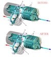
I've also included how I understand the coolant delete works.

Coolant Delete.jpg
 
Need an Induction Motor Engineer to really gain some insight on thermal degradation behavior.

Here are a few things to keep in mind
  • Less cooling requirement is EXACTLY why nearly all EV/hybrid electric motors use permanent magnet rotor in last 3 decades. Those rotors can't even be pull out of stator by hand with its magnetic field strength. Trade off is less cooling effort but using more rare earths.
  • Ceramic bearings is the latest new and expensive tech in bearings. Price is 10x+ standard high quality metal ball bearings. Was originally invented for lower resistance rather than electrical isolation and being used in many high performance applications (race bikes, trains etc) Less resistance = less heat. Ceramic balls (besides being more durable than metal balls) should also transfer less heat given its electrical isolation so the outer bearing race probably has a harder time to transfer heat to a cooled cooler rotor shaft compared to metal balls. Leading edge bearings are invisible high tech to most US population (leaders are SKF/EU->Japanese->South Korea) It's access is controlled by military security policies as they are used in the kinetic warfare weapons.
  • Electric motor rotors have naturally poor cooling paths being centered in a hot surroundings with minimal thermal pathways. Squirrel cage AC induction motor rotor are also not a single block of structureless material. Have internally laminated and metal welding structures. From the couple of induction motor thermal study papers I found, rotor heat density can surpass the stator at mid power output motors and are critical issues to study during design. Here are examples paper1 paper2. Can find many online and just about all of them focus on the rotor heat density. Rotor internal structure de-lamination and welds cracking from thermal cycling appears to be the common thermal failures resulting in loss of isolation and current flow. These failures then cascades as current changes flow from the damage to create new hot spots and develop further failure points. Incidentally, no study I've read focus on the bearings as failure points. Its always thermal analysis of the rotor and stator.
Unfortunately it doesn't matter what is the real science/engineering as LDU car don't really have any choices anyways. Tesla doesn't allow change to SDU (perm magnet rotor), provide a more robust face seal wet solution, supply key parts for the failure prone wet lip seal solution (nor document the much higher challenge to recondition the worn rotor shaft surface) and even the manifold for a dry solution. Without choices, everyone heads for what is achievable which is cutting/welding existing manifold to delete rotor coolant passage without paying Tesla $7k.
 
Based on my review of Prof Kelly's video (cued to start), I think that the cooling provided by that pipe through the rotor is more for the bearings vs the rotor.

To me, the little amount of coolant going through that pipe is not enough to provide any meaningful cooling to the rotor. Also, the copper rotor has a melting temperature of close to 2000 degrees F.

I've also included how I understand the coolant delete works.

View attachment 1026080
I stand corrected. This Tesla patent indicates rotor cooling. US7489057B2 - Liquid cooled rotor assembly - Google Patents
 
  • Informative
Reactions: blodg1
So, I did a preliminary design of the parts. The idea is to completely replace the rotor cooling tube (1006606-10-B) with a pair of parts. The lower part is basically just a feedthrough to the stator and the bottom 8mm hose connector. The upper part has the the vertical channel to feed the coolant to the upper metal cooling tube (1002731-00-A).

Since parts are very simple they can be done on even on a 2-axis CNC or a milling machine, with a single cutting tool + drilling and threading.
I assume the manufacturing cost <100$ for both.

Any comments on such design? I am planning to make a prototype next week.
So, small update:
After some thinking, measuring and testing I've ended up with the idea of a design, similar to QC.
Mine is just a bit more simple and could be done on a 2D (CNC) milling machine to make it cheaper and easier.

Also, following the cap idea discussed before, I did a drawing with the dimensions that I think fit best. The main issue is the OD of the cap, which I believe should be 55.2mm + 0.01 or 0.02 for the hot press fit.

I will be testing both options in the nearest future.

cd1-png.1027194
cd2.png


cap.png
1.png
 
So, small update:
After some thinking, measuring and testing I've ended up with the idea of a design, similar to QC.
Mine is just a bit more simple and could be done on a 2D (CNC) milling machine to make it cheaper and easier.

Also, following the cap idea discussed before, I did a drawing with the dimensions that I think fit best. The main issue is the OD of the cap, which I believe should be 55.2mm + 0.01 or 0.02 for the hot press fit.

I will be testing both options in the nearest future.

cd1-png.1027194
View attachment 1027203

View attachment 1027197View attachment 1027199
Trying to remember, do you already have a coolant leak that has triggered any codes? If so, obviously address those issues in concert with this coolant delete solution.
 
The main issue is the OD of the cap, which I believe should be 55.2mm + 0.01 or 0.02 for the hot press fit.
Yeah, that's a datum I'm looking for as well. 0.2mm interference (~0.008") seems like an awful lot. In our design exercise, I used .0025" (~.06mm) as the interference fit. But this particular metals engineering is something I don't do; I've merely watched engineers I've worked with spec this stuff.

We're ready to have a batch of ~40 made -- that's where the price-per becomes reasonable -- but that figure is still needed. My own LDU is now leaking, so I'll be moving forward with something in the next couple of months at the latest.
 
Trying to remember, do you already have a coolant leak that has triggered any codes? If so, obviously address those issues in concert with this coolant delete solution.
Not yet, but I have a high mileage Model S w. LDU, and the issue will appear sooner or later. I am preparing myself :)
Yeah, that's a datum I'm looking for as well. 0.2mm interference (~0.008") seems like an awful lot. In our design exercise, I used .0025" (~.06mm) as the interference fit. But this particular metals engineering is something I don't do; I've merely watched engineers I've worked with spec this stuff.

We're ready to have a batch of ~40 made -- that's where the price-per becomes reasonable -- but that figure is still needed. My own LDU is now leaking, so I'll be moving forward with something in the next couple of months at the latest.
Thank you for your advice, I actually was thinking that the inner diameter for the seal is 55.2, but now I measure smth around 55 (will make a precise measurement later).
I had this guess because the outer diameter of the Chenming seal is 55.2. Looks like they are just too large for the fit.
4.png
 
  • Like
Reactions: hydro
There is likely a very robust EV motor coolant seal technology that already exist. However, it is unlikely the aftermarket or DIY community can access it. But I'll post it here. Those in EU might have better luck to engage with the much more mature right to repair culture and potentially more dialog.

EKK

EKK is a $1B+ Japanese company with range of high precision capabilities. With today's global supply chain and diverse product grades. JP and EU machinery companies are focused on high precision higher sophistication products. EKK have absorbed many high precision capabilities world wide including in US and likely EU. Therefore have many development centers and several divisions to serve high end markets (aerospace, marine, semiconductor, high end machinery, and automotive) This particular seal technology is likely developed in Japan per technical paper author's location (Saitama Japan, outside Tokyo)

Patterned Surface Face Seal

They have developed a very advanced face seal directly aimed at running coolant through the rotors. In fact, many diagrams clearly refers to the problematic LDU.

This face seal has micro patterns on the sealing face to control both fluid AND aero dynamic behavior to pump the media (seal design terminology : coolant in case of LDU) constantly towards the wet side. It uses fluid dynamics at low speed and aero dynamics at high speed. If you think about how to make low friction seal, the ideal design is to have low to no fraction contact between surface. A best way to achieve this is provide a pump mechanism to constantly push the wet stuff back to prevent leaking to the dry side. ( You actually want the wet stuff near the sealing surface for lubrication and heat removal to not burn up the seal material and structure )

Bottom of the following link includes link to download 2 technical papers (require registration) that goes over in great detail on engineering design theory, testing, evaluation, and analysis of the seal. The 2nd link is much more general glossary of their capabilities. This whole field of science is called "tribology"


These designs are far beyond choosing advanced seal materials or simple lip/face seal shapes. It is creating complex fluid and aero dynamic behaviors to lubricate, cool, and pump media away from the dry side. I'd imagine requiring a significant R&D center staffed by many post graduate level skills in tribology and likely far beyond most small/medium size companies.

Likely OEM Only

Came across this design over a year ago and have been trying to reach out to this company. Their communication access in US is definitely not for end consumers or small companies. It is likely they mostly engage with large manufacturers and very high end equipment manufacturers.

They have EU subsidiary which might be more accessible if any EU member want attempt to engage. But I'm guess no standard available parts. Large OEM manufacturer engagement only. But EU's more mature right to repair culture likely create more dialog opportunity than here in US.

 
Last edited:
Not yet, but I have a high mileage Model S w. LDU, and the issue will appear sooner or later. I am preparing myself :)

Thank you for your advice, I actually was thinking that the inner diameter for the seal is 55.2, but now I measure smth around 55 (will make a precise measurement later).
I had this guess because the outer diameter of the Chenming seal is 55.2. Looks like they are just too large for the fit.
View attachment 1027353

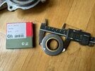
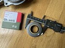
My measurements are 55.1mm @ 3 different 120 degree angles on my Ceimin seal

IMG_1631.jpegIMG_1630.jpeg

As @asavage notes, this is stainless steel rather than aluminum.

I also don't have any expertise in interference fit. But there are many online metal interference fit tables, I'm just not experienced enough to know how to interpret them or know any assumptions / caveats
 
There is likely a very robust EV motor coolant seal technology that already exist. However, it is unlikely the aftermarket or DIY community can access it. But I'll post it here. Those in EU might have better luck to engage with the much more mature right to repair culture and potentially more dialog.
It is a shame we can't source a 55mm/30mm seal like this because it is the correct application for our motors. I'd bet Tesla looked into something like this and decided it was too expensive so they stayed with the various dumpster fires we have been dealing with.
 
For anyone thats interested in pursuing a advanced face seal solution. Additional info + updates
  • Discussed with more face seal manufacturers on how to handle minute leak. Learned a bit more how water pump handles this.. It isn't just a matter of a weep hole. Dynamic (while shaft is turning) leaks from face seals (maybe also lipped seal?) are vapors Water pump has a small leak chamber with a weep hole (small diameter shaft) I guess this chamber is to condensate coolant and allow exit.
  • LDU has a spinning reluctor wheel between bearing and seal with just millimeters of space on a 30mm shaft. No idea what kind if air turbulence is created by the reluctor wheel. This likely present challenges to vacate the leaks.
Anyway, robust face seal solution likely is out of realm of possibilities for non OEM buyers. Will need the following
  • A sleeve if an off the shelf seal ID don't match. Custom part for LDU tooling is $$$$$
  • A redesigned manifold if shape can't fit in existing manifold or tolerate the blind install
  • Minute leak solution. Not sure just drilling the weep hole is sufficient with the reluctor wheel and tight geometries for a 30mm shaft
I guess probably no real option but to find out the downstream thermal cycling wear/failure of the motor components via coolant delete.
 
In case anyone wants to know whats inside the rotor


The motor production video is a Mitsubishi Electric air cooled Induction Motor (IM) common in industrial usage. See the fins at the end of the rotor and on the stator casing for cooling. Stator/rotor size is bigger than the LDU so probably can assume its higher output then LDU.

For those without electrical background. Induction is the phenomena of current transfer without direct contact (technically magnetic field is generated and current is generated). Most plugged in device in household have a transformer. Transformer works on the same induction principle, specific geometry+loops of wire windings "transfers" current from one to another without physical connection. Amount of transfer depends on the windings so there are transformers of all different input / output / ratings / sizes. Incidentally, this is why electricity and magnetism is one the same in fundamental sciences.

My understanding the rotor disks are laminated for electrical insulation. Squirrel cage bars (the rods) are welded to the rings on both ends. These are the commonly sited thermal cycling wear points in IM failure analysis : cracked welding / loss of laminate insulation. I don't know the current level running in the rotor but probably is quite significant. Current flow = heat production depending on resistance (until you get to superconductors I think... beyond my domain of knowledge)

I suppose the good news for LDU owners is... a bigger IM is not using liquid cooling. But it is using the simplest and most common forced air cooling which LDU is not with coolant delete.
 
Last edited: