


I did my 9500ci install on Thursday. I went very slow and methodically, and it went well. I did not run the read shifter, as that doesn't seem to be an issue where I live, and I did not install the LED indicator, though it would have been easy to do...a red/green LED just seemed a little out of keeping with the rest of the interior.
A couple of useful things to note: firstly, the GPS antenna works perfectly when positioned on the steel beam that runs behind the nosecone (the same beam the radar detector is mounted to). I could work out how to get it up behind the dash and behind the mesh section, but in the end having it behind the nosecone was far easier. It has a strong magnet, so no drilling required for that one. Secondly, I found a live tap inside the car that's only live when the other accessories are. It meant one less wire to run from the frunk (i.e. the fuse box), so with all the wires on the 9500ci, that's a good thing.
I felt like I took a lot of step-by-step photos, but having just reviewed them, I guess I didn't, so if you have any questions, go ahead and ask....
Step 1 - Remove frunk trim. This is really easy. I took the base mat out, then the other soft trim. All the plastic panels around the top of the frunk just pop up, you need to unscrew the rubber bolts that the frunk lid closes onto to release the side trims. As I was taking bits out, I stuck a post-it on each part with a sequence number, so I knew that putting everything back was just in reverse order.

2. The plastic trim at the front that houses the frunk light and release lever has a couple of wires going to it, they just unclip.

3. the top trim at the front with the chrome plates is held in with little plugs and a few clips. As noted elsewhere, the plugs are easy to remove, just pop the middle bit up with a flat screwdriver or spudger, then just lift it out.

4. Here's the full piece, showing the white plastic clips along the front edge.

5. Once that piece is out, the nosecone is easy to remove, as you can push it out from the inside along the top, then, holding it from underneath, lift and pull at the same time. I've marked where I think all the clips and catches were, but again, it's very easy to pop out.

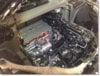
6. Now the rest of the frunk can come out. It's 2 pieces, held together and in place with, if I recall, 9mm and 10mm bolts. Remove the back section first, then the main piece just lifts out. There's a cable that runs around the left side of the frunk shell for the manual release of the frunk, so watch out for that when lifting out the frunk shell. This leaves you with a fully exposed frunk area, which makes running the cables much easier.

7. Next for the trim in the cabin. In order to remove the plastic above the pedals, you have to remove the trim for the door step, and along the side of the center opportunity area. Everything pops off fairly easy, there's no tricks. Then the panel above the pedals is held up by two screws, remove those, unclip the power lead for the footwell light, and remove the panel. I also removed the end panel of the dash, which more or les means you can work completely behind the dash, with one arm in the side, and one from underneath.

I think there's a limit on the number of photo's I can upload, so I'll stop here, and start a new post.
- - - Updated - - -
8. I installed the radar head first, on the steel beam running across the front, directly behind the nsecone. It's fairly tough to drill into, but not too bad.

9. Next up were the laser shifters. There's no ideal spot for these unfortunately, aside from behind the nosecone, if you can somehow overcome the issue of the plastic being in the way. I wasn't up for Dremmeling the nosecone, so they're mounted in the top vent under the cone.

10. I didn't want to cut into the grid, but I also didn't want the shifters sticking out too far, so I had to cut away a bit of the grid (using wire snips - it's very soft plastic) to allow the back corner of each of the shifters to be recessed a little. As I'm using the underside of the nosecone to mount the shifters, I couldn't move them further back to be completely out of sight, as I would have lost my mounting point.

11. For now I've just used very strong foam tape (VHB tape) to mount them to the cone, mostly because I want to make sure they're in the right spot before drilling holes, but, the tape is strong, so chances are good I'll see how it goes before screwing them to the nose cone. The red line in the photo is just my laser level, not a cool Knight Rider effect")

11. Next I put the GPS antenna on the steel bar, fairly close to the red battery jump bolt (no picture, sorry). It has a VERY strong magnet, it's not going anywhere.
12. Now gather all the wires (4 - laser x 2, radar, GPS), and wrap them in electrical tape. I decided not to drill through the firewall (there's no openings that I could see to be used), so I ran it along the drivers-side wing, and into the passenger compartment by going underneath the door seal.


A couple of useful things to note: firstly, the GPS antenna works perfectly when positioned on the steel beam that runs behind the nosecone (the same beam the radar detector is mounted to). I could work out how to get it up behind the dash and behind the mesh section, but in the end having it behind the nosecone was far easier. It has a strong magnet, so no drilling required for that one. Secondly, I found a live tap inside the car that's only live when the other accessories are. It meant one less wire to run from the frunk (i.e. the fuse box), so with all the wires on the 9500ci, that's a good thing.
I felt like I took a lot of step-by-step photos, but having just reviewed them, I guess I didn't, so if you have any questions, go ahead and ask....
Step 1 - Remove frunk trim. This is really easy. I took the base mat out, then the other soft trim. All the plastic panels around the top of the frunk just pop up, you need to unscrew the rubber bolts that the frunk lid closes onto to release the side trims. As I was taking bits out, I stuck a post-it on each part with a sequence number, so I knew that putting everything back was just in reverse order.
2. The plastic trim at the front that houses the frunk light and release lever has a couple of wires going to it, they just unclip.
3. the top trim at the front with the chrome plates is held in with little plugs and a few clips. As noted elsewhere, the plugs are easy to remove, just pop the middle bit up with a flat screwdriver or spudger, then just lift it out.
4. Here's the full piece, showing the white plastic clips along the front edge.
5. Once that piece is out, the nosecone is easy to remove, as you can push it out from the inside along the top, then, holding it from underneath, lift and pull at the same time. I've marked where I think all the clips and catches were, but again, it's very easy to pop out.
6. Now the rest of the frunk can come out. It's 2 pieces, held together and in place with, if I recall, 9mm and 10mm bolts. Remove the back section first, then the main piece just lifts out. There's a cable that runs around the left side of the frunk shell for the manual release of the frunk, so watch out for that when lifting out the frunk shell. This leaves you with a fully exposed frunk area, which makes running the cables much easier.
7. Next for the trim in the cabin. In order to remove the plastic above the pedals, you have to remove the trim for the door step, and along the side of the center opportunity area. Everything pops off fairly easy, there's no tricks. Then the panel above the pedals is held up by two screws, remove those, unclip the power lead for the footwell light, and remove the panel. I also removed the end panel of the dash, which more or les means you can work completely behind the dash, with one arm in the side, and one from underneath.
I think there's a limit on the number of photo's I can upload, so I'll stop here, and start a new post.
- - - Updated - - -
8. I installed the radar head first, on the steel beam running across the front, directly behind the nsecone. It's fairly tough to drill into, but not too bad.
9. Next up were the laser shifters. There's no ideal spot for these unfortunately, aside from behind the nosecone, if you can somehow overcome the issue of the plastic being in the way. I wasn't up for Dremmeling the nosecone, so they're mounted in the top vent under the cone.
10. I didn't want to cut into the grid, but I also didn't want the shifters sticking out too far, so I had to cut away a bit of the grid (using wire snips - it's very soft plastic) to allow the back corner of each of the shifters to be recessed a little. As I'm using the underside of the nosecone to mount the shifters, I couldn't move them further back to be completely out of sight, as I would have lost my mounting point.
11. For now I've just used very strong foam tape (VHB tape) to mount them to the cone, mostly because I want to make sure they're in the right spot before drilling holes, but, the tape is strong, so chances are good I'll see how it goes before screwing them to the nose cone. The red line in the photo is just my laser level, not a cool Knight Rider effect
11. Next I put the GPS antenna on the steel bar, fairly close to the red battery jump bolt (no picture, sorry). It has a VERY strong magnet, it's not going anywhere.
12. Now gather all the wires (4 - laser x 2, radar, GPS), and wrap them in electrical tape. I decided not to drill through the firewall (there's no openings that I could see to be used), so I ran it along the drivers-side wing, and into the passenger compartment by going underneath the door seal.
Attachments
Last edited: