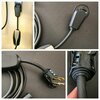
Got an early UMC from a friend with visible melted plastic between the connector and the 14-50 adapter. During charging the AMPs would drop to 20 and clearly was not safe to continue using it that way.
By the way, here is a disclaimer:
I shall not be held responsible for any damage to hardware or persons that may arise from following the post below. Use this post and the information herein at your own risk. What I describe here is a modifications to electrical and electronic device. Do not attempt to follow anything listed below unless you are competent to do so, as you could get a serious electric shock or even electrocution if you do not know what you are doing. If you are in any doubt about your ability to perform a certain task, then get someone else who is competent to do it for you. Make sure any item you are working on is powered off and unplugged from the mains before starting work. I repeat, use this post and the information herein at your own risk.
Many thanks to MPT for his advice.
Here is the patient...

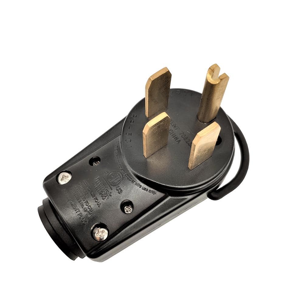
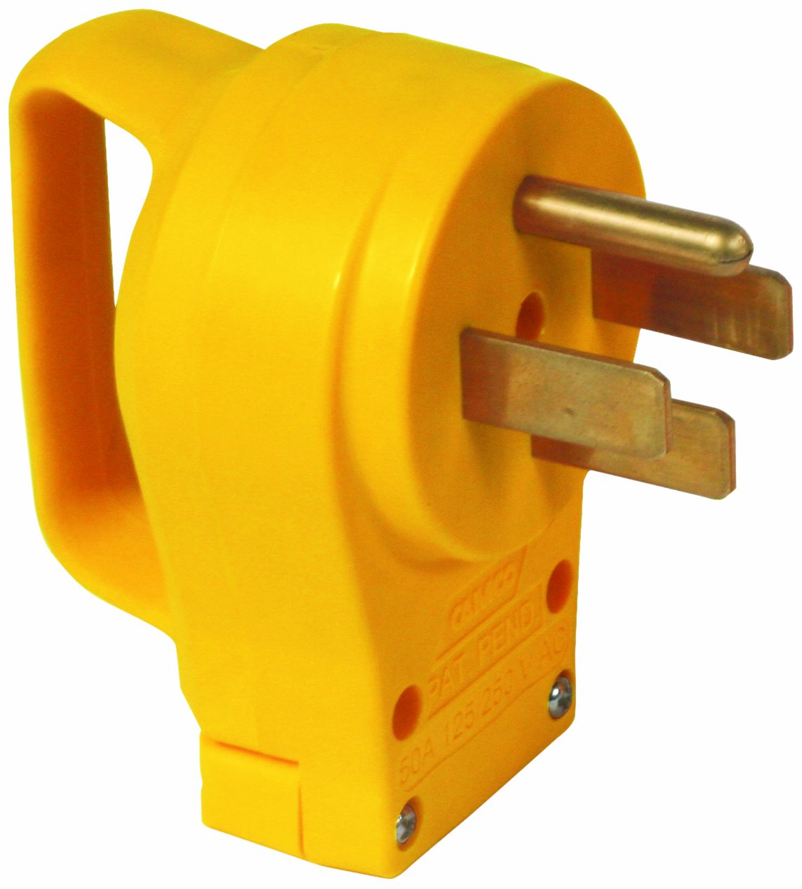
Instead of throwing it away, I decided to cut the melted connector away and replace it with a Camco 50 AMP replacement plug ($15 at Amazon).
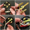
After having cut the connector off, you are presented with the following:
2 Red wires
2 Black wires
1 Green/Yellow wire
1 tiny purple or maroon wire
1 tiny blue wire
The Red and the Black wires are the two hots and go on the two opposing blades while the green is the Ground and goes to the round prong.
There is no Neutral in the UMC so the bottom blade does not get connected to anything.
Now for the tiny wires; the blue is not needed but the purple/maroon wire is needed to signal the Amperage required.
This is the table: (Courtesy of various TMC members)
40 amps - 9.08k ohms
24 amps - 33.16k ohms
16 amps - 75k ohms
12 amps - 140k ohms
Since the gaps between steps are fairly large I figured that a 1ok ohms resistor would do and to be safe I looked for the highest wattage possible at Radio Shack and came up with this pack of 5

They all measured about 9.7k ohms so I picked the closest to the desired value of 9.08k ohms
I simply twisted the resistor in line between Ground and the purple and wrap it with electrical tape but it would't be a bad idea to solder it.

Once plugged in green light goes on (otherwise you'll get a red one)

Charging well at 40 AMP 231V

By the way, here is a disclaimer:
I shall not be held responsible for any damage to hardware or persons that may arise from following the post below. Use this post and the information herein at your own risk. What I describe here is a modifications to electrical and electronic device. Do not attempt to follow anything listed below unless you are competent to do so, as you could get a serious electric shock or even electrocution if you do not know what you are doing. If you are in any doubt about your ability to perform a certain task, then get someone else who is competent to do it for you. Make sure any item you are working on is powered off and unplugged from the mains before starting work. I repeat, use this post and the information herein at your own risk.
Many thanks to MPT for his advice.
Here is the patient...
Instead of throwing it away, I decided to cut the melted connector away and replace it with a Camco 50 AMP replacement plug ($15 at Amazon).
After having cut the connector off, you are presented with the following:
2 Red wires
2 Black wires
1 Green/Yellow wire
1 tiny purple or maroon wire
1 tiny blue wire
The Red and the Black wires are the two hots and go on the two opposing blades while the green is the Ground and goes to the round prong.
There is no Neutral in the UMC so the bottom blade does not get connected to anything.
Now for the tiny wires; the blue is not needed but the purple/maroon wire is needed to signal the Amperage required.
This is the table: (Courtesy of various TMC members)
40 amps - 9.08k ohms
24 amps - 33.16k ohms
16 amps - 75k ohms
12 amps - 140k ohms
Since the gaps between steps are fairly large I figured that a 1ok ohms resistor would do and to be safe I looked for the highest wattage possible at Radio Shack and came up with this pack of 5
They all measured about 9.7k ohms so I picked the closest to the desired value of 9.08k ohms
I simply twisted the resistor in line between Ground and the purple and wrap it with electrical tape but it would't be a bad idea to solder it.
Once plugged in green light goes on (otherwise you'll get a red one)
Charging well at 40 AMP 231V