I'm not a machinist, but I've seen what can happen when you are trying to press-fit parts together and one of them is cast aluminum.... Bang. I'd be surprised if it took that much to press it together at .003, that you will get .006 to fit at all without destroying it..
@jatguy used ~.0075" (.19mm) and hasn't (yet) suffered casting failure
")
why not mill in an o-ring groove in the bottom of it to match the bottom of the bore and make it a permanent captured viton seal?
It was considered early on. Problems:
An o-ring is a part that has to be able to be serviced.
You have to retain the plug in the bore via external means. Staking? Has to be un-staked to service.
Do we drill/tap for retaining screws? Outside the bore? Ugh. In the plug itself? Possible leak point.
I like o-ring seals, but not here.
just a touch of rtv n ur good to go. system only has like 5psi max...
I'm certain that .003" (~.08mm) oversize and any kind sealant would be fine.
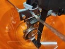
As an example, this plug will
not come out at 30 PSI, the max for my test gauge; I'll be removing the test gauge this morning, plugging the tee, and using higher pressure to remove the plug. .003" is a good fit, but with the seal counterbore's standard finish, I wanted to see how reliably this could seal without sealant, and I have my answer: not.
The system is more or less unpressurized; the only pressure differential is provided by that little coolant pump, which is designed more for volume than pressure.
I could remove the current .003" plug, apply sealant, and reinstall it, but I want to try a tighter fit as well, while I have a coolant manifold in my hand.
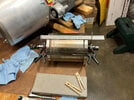
I like your pressure test system. I'll try that.
Can you believe it took almost an entire day to put together? I didn't have a 1/4-18 NPT tap, the bandsaw needed attention, I misplaced my gasket material, the lowest range gauge I had was too high range so I bought another (I settled on 0-30 PSI), and I had to adapt that RV blow-down adapter with the Schraeder valve, from GHT to NPT. And buy the cheap Chinese Irwin C-clamp to retain the large rubber stopper, as I couldn't fit two bar clamps in place at once, and my collection of C-clamps were all too large as well.
It's a bunch of stuff thrown together but it was a bit of fun at the end . . . just more time than I'd have liked.
---
Some math notes for me to refer to in future:
For 55mm OD aluminum cap the temperature difference of 100 degrees gives you the expansion of approx. 0.1-0.12 mm.
So if you want to squeeze the 55.12mm cap to the 55.0mm hole one will need to heat up the hole (or cool down the cap/shaft) by 100 degrees.
This is unfamiliar territory for me, so watch for mistakes . . . primary school math here . . .
Per °C: 6061 has an expansion rate of approx. [23.4 µm/m]: 23.4 * 10^-6/m/°C = .000023m/m/°C = .023mm/meter/°C
For our 55mm part, each °C:
.023mm/meter/°C / 55mm [seal counterbore] = .023mm * (55mm/1000mm) = .001265mm/m/°C
For 100°C:
.001265mm/°C * 100°C = .13mm
(~.005" for 212°F)
Working the other way 'round, I'd been using ~.002" per 100°F, so . . . close enough.
I bought some dry ice (~-108°F surface temp, so at "room temperature" I had -- on paper -- ~180°F temperature differential with the manifold not heated supplementarily) the day before yesterday, but I was unable to obtain sufficient thermal transfer to achieve anything close to "fall out" of the .003" plug from the manifold; the thermal conductivity of aluminum being what it is (excellent), I couldn't achieve sufficient temperature differential between the plug and the manifold. This implies that cooling the plug/heating the manifold may work well as an aid for installation (if one works sufficiently quickly) but isn't of benefit for disassembly . . . not that anyone except myself would want to disassemble it