What size is your main breaker? Also, what size is the transformer feeding your property?
While I always want to know this personally, it really is not your problem. If you overload it and it fails, it is the utilities problem. If voltage drops too much during high load times of day or is otherwise of poor quality, just call and complain until they fix it (this applies to transformer sizing and conductor sizing to the house). The power company does not have to comply with the national electrical code, they pretty much can do whatever they want. Some utilities have ancient tiny wires feeding a ton of houses off one transformer, others (like Portland General Electric) do a fantastic job.
A good utility will be monitoring total load on your transformer by knowing what all meters are hooked to what transformer. They can generate reports of what likely needs upgraded.
Dialing down the wall connector is not enough by itself.
Dave and I will respectfully disagree on this point. If you have a proper load calculation done and you determine that 80a (64a continuous to the car) is too much for your existing electrical service, then I would just turn the rotary dial down to an appropriate setting to keep the overall load calculations below the limit. As long as the wire is sufficient for the 80a breaker, I would not swap the breaker. This gives you the ability to later turn it back up easily if other conditions change in the house (like converting a dryer to gas, or a range, or a water heater, etc...) I am firm in my belief that this is fully code compliant since the load calculations are done on "the load to be served" and have nothing to do with the size of installed breaker. Changing the rotary dial down is a rock solid way to limit "the load to be served" and it is done in such a way that a user is not going to generally arbitrarily change.
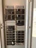
A lot of this conversation is over my head, but here are a few pictures of my box before the electrician installed the 80A Circuit. Does this add any valuable information?
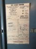
Wow, I think I was literally just this evening in an identical panel to this one helping a coworker of mine. It is a Square D QO style panel in a "split bus" configuration. The top six double breaker positions (so 12 breaker positions) are directly hooked to the incoming service wire. They are all considered "service disconnects". You can not have more than six total and so that is why you are not supposed to use single wide breakers in these positions (without a handle tie). More pictures would be great (of the stickers on the inside panel door, of the breakers themselves so we can read all the breaker sizes, of the list of what all the breakers are for aka panel schedule, and particularly of any stickers inside the sidewalls of the breaker pan/can).
If it is identical to the one I was in tonight, it is actually a 200a panel (it was very common to have these split bus panels for 200a services since the 200a breakers were expensive). So charging your car at the full 48a charge rate (takes up 60a of capacity due to it being considered a "continuous load") is likely very doable if that is the case. To the untrained eye, I think you may have 4/0 wire feeding that panel which is what the code requirement is for a 200a service (though it is very old wire). Can you read anywhere on that main thick cable what size it says it is? (may be embossed on the sheath).
I am very concerned that somehow the 60a breaker blew. Has that *ever* happened before? The car should have no impact on that. My concern is that perhaps the new breaker has a bad connection to the bus, or the bus has an issue, or the bolt to the main lugs or the main lugs connection to the main service wires has an issue that is causing heat to build up. Heat from the main terminal lugs or a bad breaker connection could conduct down the bus and cause the 60a breaker to false trip. (that is where I would pull out my Flir camera!)
Can you also give us a rundown of the major appliances in your house? Do you have a gas or electric water heater? Gas or electric dryer? Gas or electric furnace/wall heaters? Gas or electric range? You said you have AC? Basically we have four 240v breakers to identify if they are in use or not and how much they might draw.
At the end of the day, you need to figure out what your total service capacity is (hopefully 200a), and then you need an accurate load calculation done. Then if necessary, crank the Wall Connector down to fit under that "cap". Separate from that, you need to figure out why that 60a breaker blew. Safest thing to do would be to call an electrician. I personally would use my amp meter to measure stuff to see what is actually being drawn, I would use my flir camera with it under load to see what is heating up, and I would check the tightness of all the key connections (but this is hard to do safely since you have no easy way to de-energize the top half of your bus).
Good luck and please report back what you find!
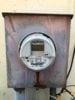
P.S. And it would be interesting to see pictures of your external meter and mast / wires back to the utility transformer and to get an estimate of how far it is, what size wires they are, and how many other houses are connected. But that really has nothing to do with your current breaker tripping issue. It would more come into play if voltage drop was too high.