Hi folks, I've just stumbled upon this thread looking for a good solution to repair my LDU. And I'm thinking of creating a pair of parts to replace the rotor cooling tube - similar to QC Charge mod, which I find a bit complicated from the fabrication point of view.
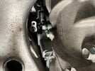
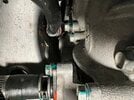
I explain it on the photo of @OhMYLRdy!
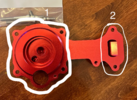
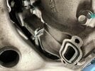
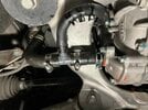
The bottom inlet (2) could be replaced with a simple part guiding the coolant directly to the inner stator loop. On the bottom a simple push-in hose connector could be added, to connect parts (1) and (2) in between with short a PVC hose.
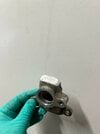
The top cover (1) could be just a cap of specific form covering the rotor axle, with a simple internal coolant guide from the push-in hose to a metal cooling tube (1002731-00-A).
What do you think about this idea? I could make CADs for such solution and believe it could be easily CNC-machined for 100-150$ since parts are quite simple.
Could there be any potential issues running the rotor without a coolant at all?
I explain it on the photo of @OhMYLRdy!
The bottom inlet (2) could be replaced with a simple part guiding the coolant directly to the inner stator loop. On the bottom a simple push-in hose connector could be added, to connect parts (1) and (2) in between with short a PVC hose.
The top cover (1) could be just a cap of specific form covering the rotor axle, with a simple internal coolant guide from the push-in hose to a metal cooling tube (1002731-00-A).
What do you think about this idea? I could make CADs for such solution and believe it could be easily CNC-machined for 100-150$ since parts are quite simple.
Could there be any potential issues running the rotor without a coolant at all?