I don't have the breadth of experience with many LDU stators to give good advice on what is "good" HV isolation resistance. I'm seeing numbers quoted from 4Mohm to 120Mohm, which is quite a large range. I think that some numbers are coming from repair facilities that have a strong incentive to disqualify a stator that isn't comfortably above a minimum. Sorry in advance: lots of words follow . . .
Backing out a bit and looking at the entire HV system, the
Tesla Isolation Faults guide says (pg. 6) that during various test procedures using the diagnostic menu or TDS (which utilizes the BMS for measurements, and therefore only measures at the
battery side of the contactors), HV contactors open, that part of the system must remain above 1.8Mohm. Put another way, with the contactors open, that's measuring the isolation of the battery only.
[My understanding is that on the RAV4 EV (which is basically a Model S) the BMS will refuse to close contactors if it sees all isolation <1Mohm; if the contactors are allowed to close, and the isolation resistance drops under 1Mohm, the BMS opens the contactors and faults.]
On pg. 10, it states that "healthy" iso resistance is >3Mohm with contactors open, >2Mohm with contactors closed :
View attachment 1049208
Later in the document, various components being
tested independently by Fluke 1507/1587 have to pass these thresholds (pg. 11):
View attachment 1049209
Note that the LDU is not listed above.
But none of those values in that last chart are for the bare stator windings: there is no test from Tesla for the stator. If the inverter is not in driving mode (powering the stator), then the inverter's IGBTs don't have the stator in circuit, and I don't see how the stator's iso can be tested independently (ie via an insulation resistance tester/megger/Fluke15x7) without accessing the stator windings bolts that I mentioned above, under the orange cover mid-gearbox front (rear, on RAV4 EV).
The first chart above says the entire system must be >2Mohm when "in Drive" or driving or inverter supplying power to the stator, but that's the entire system; each HV component "leaks" a bit, so you'd want any one component to be well above that.
---
I had
one HV contactor opening incident, in Feb, when I demanded a bit more power than usual. More power = the inverter sends higher voltage & current to the stator, and like a clutch that slips only when you step on the gas, the stator's isolation resistance breaks down when faced with higher voltage. That's why you can't use a DMM's ohmmeter setting to validly check for insulation resistance: it doesn't challenge the insulation with HV! A "megger" (megohmmeter) or Insulation Resistance Tester (like the Fluke 15x7) put 500v on the windings and stress tests the insulation.
A DMM puts almost no voltage on the windings, and is pretty much useless for testing for isolation resistance of HV components, unless they are so badly damaged that they are completely shorted: well below test threshold. Passing a DMM ohmmeter test means nearly nothing.
After resetting the car, it drove fine for another 50 miles, whence I parked it until removal of the LDU.
My somewhat-dry stator, which had suffered coolant intrusion, measured 4.7Mohm after water/soap washing on an incline as shown previously and having had a small heater blowing air into it for about ten days: nothing very vigorous, and certainly not as much effort as I'd planned to do, because I considered 4.7Mohm to be "good enough" for my purposes. I had started with ~3Mohm before disassembly. I estimate that about two tablespoons of coolant were distributed around the reluctor wheel, the rotor's outer bearing, and the stator cavity. There was NO moisture on the inboard end of the stator.
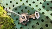
Ugly on the stator outboard end:
View attachment 1049223
Lots of corrosion on the stator outboard end, and visible damage of the (awful, waxy, non-epoxy) stator potting compound:
View attachment 1049224
Moderate corrosion to 1/2 the stator laminations:
View attachment 1049225
Dry, but with some evidence of previous coolant on the stator inboard end:
View attachment 1049226
Measuring with the stator/inverter bolts installed, or removed and the windings' leads isolated (by using thin bent plastic strips behind the stators' leads) made almost no difference to that 4.7Mohm reading. If I'd had a leaky IGBT or coolant in the power section, this would have been different, but my coolant never made it to the center "tunnel" much less the inverter side, lucky me.
After reassembly and installation, the BMS reports
total HV system iso as 3.3Mohm.
I would have preferred that the stator windings' iso be above 6Mohm, but in practice I'm content that I have no (or miniscule: difficult to remove inside the windings) residual water. I may live to regret not stripping the gearcase and soaking the stator half of the assy. in 99% IPA to dilute and "wash away" the remainder, but I'm taking a calculated risk by not doing so. I left no visible coolant, and removed all the corrosion I could reach without completely stripping the gearcase. Coolant could continue to degrade the iso, and there's little chance that remaining water will "evaporate" because there is almost no air exchange in the stator cavity. Time will tell if I get away with not having gone further.